Table of Contents
Advertisement
Quick Links
Installation, Operation, and Maintenance
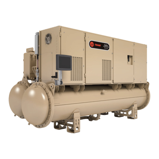
Agility™ Water-cooled Chillers
With Symbio™ Controls
Model: HDWA PC 747
Only qualified personnel should install and service the equipment. The installation, starting up, and servicing of heating, ventilating, and air-conditioning equipment
can be hazardous and requires specific knowledge and training. Improperly installed, adjusted or altered equipment by an unqualified person could result in death or
serious injury. When working on the equipment, observe all precautions in the literature and on the tags, stickers, and labels that are attached to the equipment.
September 2023
SAFETY WARNING
HDWA-SVX002C-EN
X39641412003
Advertisement
Table of Contents

Subscribe to Our Youtube Channel
Related Manuals for Trane Technologies Agility HDWA PC 747


Summary of Contents for Trane Technologies Agility HDWA PC 747
- Page 1 Installation, Operation, and Maintenance Agility™ Water-cooled Chillers With Symbio™ Controls Model: HDWA PC 747 X39641412003 SAFETY WARNING Only qualified personnel should install and service the equipment. The installation, starting up, and servicing of heating, ventilating, and air-conditioning equipment can be hazardous and requires specific knowledge and training. Improperly installed, adjusted or altered equipment by an unqualified person could result in death or serious injury.
- Page 2 Introduction Read this manual thoroughly before operating or servicing WARNING this unit. Proper Field Wiring and Grounding Required! Warnings, Cautions, and Notices Failure to follow code could result in death or serious Safety advisories appear throughout this manual as injury. required.
- Page 3 Introduction WARNING condenser, control panel, compressor/motor, economizer, factory-mounted starter or any other components originally Follow EHS Policies! attached to the fully assembled unit— compliance with the Failure to follow instructions below could result in following is required to preserve the factory warranty: death or serious injury.
-
Page 4: Table Of Contents
Table of Contents Unit Nameplate ......7 Refrigerant Pressure Relief Valve Venting . - Page 5 Table of Contents Programming......41 Stopped to Starting — Heating Mode....... . 55 Building Automation Systems .
- Page 6 Table of Contents Appendix C: Settings ..... . . 75 Unit Start-up/Commissioning ....72 Appendix B: Chiller Installation Completion Appendix D: Operator Log .
-
Page 7: Unit Nameplate
Unit Nameplate The unit nameplate is located on the right side of the Figure 1. Typical unit nameplate control panel. A typical unit nameplate is illustrated in the following figure and contains the following information: • Unit model and size descriptor •... -
Page 8: Compressor Nameplate
Unit Nameplate Compressor Nameplate Figure 2. Compressor nameplate The compressor assembly has a separate model number which is required to identify internal and external compressor parts. The model number begins with “HDMA” and the nameplate is located on the interstage pipe; refer to “,”. -
Page 9: Model Number Descriptions
Model Number Descriptions Digit 1, 2 — Unit Function Digit 15 — Evaporator Shell Size Digit 23 — Evaporator Expansion Valve HD = Agility™ Centrifugal Water-cooled Chiller A= 020A Evaporator Shell A = 400 C = 040A Evaporator Shell B = 200 S = Special S = Special Digit 3 —... - Page 10 Model Number Descriptions Digit 33 — Control Power Transformer (CPTR) 0 = Without CPTR S = Special Digit 34 — Thermal Dispersion Water Flow Proving 0 = None, Customer to Provide Device for Condenser and Evaporator A = Thermal Dispersion Water Flow Proving Selected for Condenser and Evaporator HDMA Centrifugal Compressor Description Adaptive Frequency Drive Description...
-
Page 11: General Information
General Information Unit Description inlet and outlet openings are covered before shipment. The unit ships charged with refrigerant. Agility™ chillers are centrifugal, water-cooled liquid chillers designed for indoor installation. Each unit is a completely Component Locations assembled, hermetic package that is factory-piped, wired, leak-tested, dehydrated, charged, and tested for proper Chiller control operation before shipment. -
Page 12: Adaptive Frequency Drive
General Information Figure 4. Typical Agility chiller component location (back view) Compressor Discharge Check Valve Output Filter (200T Only) Relief Valves Condenser Water Outlet Compressor Condenser Compressor Motor Water Inlet Bearing Controller Evaporator Evaporator Water Outlet Evaporator Water Inlet Adaptive Frequency Drive Figure 6. -
Page 13: Unit Clearances
General Information Unit Clearances Figure 7. Clearance requirements, in. (cm) (91) Right-hand tube pull shown; apply tube pull clearances dimension to the left end for left-hand tube pull. This dimension per NEC Article 110. 34.3 (87.2) Radius 41 (104) 130 (330) 300 (762) (92) Dim. -
Page 14: Dimensions And Weights
General Information Dimensions and Weights Table 1. Agility chiller weights (lb) Dimensions Shipping Weight Operating Shell With Without Weight Refer to unit submittals for specific chiller dimensions and Refrigerant Refrigerant water connection locations. Minimum 10100 9575 14087 Unit Specifications—Imperial (I-P) Units Maximum 12302 11777... -
Page 15: Unit Specifications-International
General Information Unit Specifications—International Center of Gravity (mm) System (SI) Units Table 4. Agility chiller center of gravity (mm) Weights (kg) Shipping Operating Important: The weight information provided here should be used for general information only. For specific Mini- 1007 1011 weights for your chiller, refer to your submittal package. -
Page 16: Pre-Installation
Pre-installation ASHRAE Standard 15 Loose Parts Inventory Compliance Check all items against the shipping list. Display, display arm and mounting, water vessel drain plugs, isolation pads, Trane recommends that indoor Agility™ chiller installations Air-Fi®, Wi-Fi, LTE modem, and other optional components fully meet or exceed the guidelines of the current version of are shipped loose in the parts box. - Page 17 Pre-installation Note: The chiller should remain within its protective shrink- wrap covering during storage. Trane Supplied Trane Supplied Field Supplied Type of Requirement Trane Installed Field Installed Field Installed Foundation • Meet foundation requirements • Safety chains Rigging • Rigging shackles •...
-
Page 18: Installation: Mechanical
Installation: Mechanical Location Requirements generated by unit operation from the equipment room. Ventilation must be adequate to maintain an ambient Sound Considerations temperature lower than 104°F (40°C). Vent the evaporator, condenser, and compressor pressure • Install rubber vibration isolators in all water piping. relief valves in accordance with all local and national •... -
Page 19: Adaptive Frequency Drive Enclosure
Installation: Mechanical NOTICE • Maximum elevation at which drive can operation is 9842.5 ft (3000 m). Equipment Damage! • Non-corrosive location. Failure to protect the unit from freezing could result in • Verify that the drive location will meet the equipment damage. -
Page 20: Standard Chiller Lift
Installation: Mechanical Special Lift Requirements NOTICE Wiring Damage! NOTICE Damage to unit wiring could result in equipment Equipment Damage! failure. Moving the chiller using a fork lift could result in Care must be taken during rigging, assembly and equipment or property-only damage. disassembly to avoid damaging unit wiring. -
Page 21: Spring Isolators
Installation: Mechanical Spring Isolators Foot pocket size information is shown in the following table and figure. Spring isolators are sometimes considered for chiller installations is where vibration transmission is of concern. Table 7. Spring isolator foot pocket size Spring isolators are typically not needed for Agility chillers Width (in) Length (in) Height (in) -
Page 22: Venting
Installation: Mechanical Figure 12. Leveling the chiller (front and left views) Figure 13. Leveling the chiller (tooling hole) All HDWA chillers use evaporator and condenser pressure relief valves (refer to the following figure) that must be vented to the outside of the building. Figure 14. - Page 23 Installation: Mechanical Pressure relief valve discharge capacities varies with shell required by ASHRAE Standard 15-94. Do NOT adjust relief diameter and length and also compressor displacement. valve setting in the field. Discharge venting capacity should be calculated as Table 8. Pressure relief valve data Discharge Setpoint Rated Capacity Field Connection Pipe Size...
-
Page 24: Freeze Protection
Installation: Mechanical Freeze Protection and recommended ethylene glycol and propylene glycol solution strengths. For unit operation in a low temperature environment, • LRTC = Leaving Refrigerant Temperature Cutout adequate protection measures must be taken against freezing. Refer to the following tables for adjusted settings •... - Page 25 Installation: Mechanical Table 10. Agility chiller control settings based on propylene glycol percentage (continued) Solution Freeze Point Minimum Recommended LRTC Minimum Recommended LWTC Propylene Glycol Percentage, % °F °C °F °C °F °C 17.6 -8.0 14.2 -9.9 19.6 -6.9 15.7 -9.0 12.3 -10.9...
-
Page 26: Installation: Water Piping
Installation: Water Piping Overview Valves – Drains and Vents NOTICE The following water piping circuits must be installed and connected to the chiller: Waterbox Damage! • Pipe the evaporator into the chilled water circuit. Failure to follow instructions could result in damage •... -
Page 27: Strainers
Installation: Water Piping Strainers Figure 15. Installation of ifm efector flow detection controller and sensor NOTICE Water Borne Debris! If factory-provided, To prevent components damage, pipe strainers must located in control panel. be installed in the water supplies to protect components from water borne debris. - Page 28 Installation: Water Piping section of pipe. The maximum distance from the control 6. Remove all air from the piping circuit prior to adjusting panel must not exceed 29.5 ft (9 m) (see item labeled the low water flow setpoint. “1” in the preceding figure). Allow at least five pipe 7.
-
Page 29: Evaporator And Condenser Water
Installation: Water Piping Evaporator and Condenser Figure 19. Typical condenser water piping circuits Water Piping The following two figures illustrate the recommended Outlet (typical) water piping arrangements for the evaporator and condenser. Figure 18. Typical evaporator water piping circuit Inlet Outlet 1. -
Page 30: Water Piping Connections
Installation: Water Piping thermometers, flexible connectors, and any removable pipe Figure 20. Typical grooved pipe connection spools. Ensure that the evaporator water piping is clear; check it after the chilled water pump is operated but before initial chiller start-up. If any partial blockages exist, they can be detected and removed to prevent possible tube damage resulting from evaporator freeze-up or erosion. -
Page 31: Grooved Pipe Coupling
Installation: Water Piping Notes: Notes: • If waterboxes are reversed, be sure to properly • Refer to the coupling manufacturer’s guidelines rewire water temperature sensors in the control for specific information concerning proper panel. piping system design and construction methods for grooved water piping systems. -
Page 32: Victaulic Gasket Installation
Installation: Water Piping Figure 22. Modifying 300 psig (2068.4 kPaG) flange 4. Open fully and place hinged Victaulic® flange around adaptors for flat-faced flange application the grooved pipe end with the circular key section locating into the groove. Remove to mate 5. -
Page 33: Pressure Testing Waterside Piping
Installation: Water Piping Figure 24. Flange screw tightening sequence (8 or 12 Waterside design pressure is 150 psig (1034.2 kPaG) or screws) 300 psig (2068.4 kPaG); refer to unit nameplate or to submittal documentation. Eddy Current Testing Trane recommends conducting an eddy current inspection of the condenser and evaporator tubes in water-cooled chillers every three years. -
Page 34: Insulation
Insulation Unit Insulation Requirements Table 14. Agility chiller insulation requirements 3/4 in. (19.05 mm) Insulation, Factory-installed insulation is available as an option for all Location Square Feet (Square Meters) units. Factory installation does NOT include insulation of 020A Evaporator, suction elbow, the chiller feet. - Page 35 Insulation Figure 25. Recommended area for unit insulation Notes: • Bulbwells, drain, and vent connections must be accessible after insulating. • All units with evaporator marine waterboxes: wrap waterbox shell insulation with strapping and secure strapping with seal. • Evaporators with ASME nameplates must have insulation cut out around the nameplate. Do NOT glue insulation to the nameplate.
-
Page 36: Electrical Requirements
Electrical Requirements Installation Requirements NOTICE Adaptive Frequency Drive (AFD)/Starter WARNING Component Damage! Proper Field Wiring and Grounding Failure to remove debris from inside the AFD/starter Required! panel could result in an electrical short and could Failure to follow code could result in death or serious cause serious AFD/starter component damage. -
Page 37: Adaptive Frequency Drive
Electrical Requirements WARNING Table 16. Adaptive Frequency Drive (AFD) electrical data — XT circuit breakers 460/480 and 575/ Personal Protective Equipment (PPE) 600 volts Required! Short Circuit Line Input XT Breaker Maximum Withstand Connection Failure to wear PPE and follow proper handling Voltage AIC Amps Rating... -
Page 38: System Control Circuit Wiring
Electrical Requirements System Control Circuit Wiring (Field Wiring) Figure 26. HDWA Agility chiller field wiring NOTES: CLASS 1 FIELD WIRING INSULATION RATING IS REQUIRED TO BE EQUAL TO OR BE GREATER THAN THE EQUIPMENT SUPPLY VOLTAGE RATING. CLASS 2 FIELD WIRING INSULATION IS REQUIRED TO BE RATED AT 300V MINIMUM. -
Page 39: Sensor Circuits
Electrical Requirements Table 19. Unit control panel wiring 120 Vac Standard Control Circuits: Unit Control Panel Control Wiring Input or Output Type Unit Control Terminations Contacts (120 Vac) Evaporator Water Flow Switch Binary Input Normally Open, Closure with Flow 1K11-J3-1 to 2 Binary Input Normally Open, Closure with Flow Condenser Water Flow Switch... - Page 40 Electrical Requirements Figure 27. Agility chiller sensor locations Detail A See Detail A See Detail B Detail B 1. 4P1, Tracer® AdaptiView™ display 2. 4BT3, Condenser entering water temperature 3. 4BT6, Condenser leaving water temperature 4. 4BT2, Evaporator entering water temperature 5.
-
Page 41: Schematic Wiring Drawings
Electrical Requirements 13. 4BP2, Condenser pressure 14. 4BT7, Compressor discharge temperature 15. 4BT8, Economizer leaving refrigerant temperature 16. 4M2, Evaporator EXV 17. 4M4, Economizer EXV 18. 4M6, Drive cooling EXV 19. 4BT4, Drive cooling supply temperature 20. 4M5, Inlet guide vane second stage actuator 21. - Page 42 Electrical Requirements Ensemble, Tracer SC+, or a third party building automation system that supports LonTalk. HDWA-SVX002C-EN...
-
Page 43: Installation: Controls
Installation: Controls Overview Tracer TU serves as a common interface to all Trane chillers, and will customize itself based on the properties of Agility™ model HDWA units utilize the following control/ the chiller with which it is communicating. Thus, the service interface components: technician learns only one service interface. - Page 44 Installation: Controls Under optimal conditions, it can restart in as little as 45 (UPS). An 80 percent cooling load can be achieved in less seconds with no need for uninterrupted power supply than 2.5 minutes after power restoration. HDWA-SVX002C-EN...
-
Page 45: Adaptiview Control Panel
Installation: Controls AdaptiView Control Panel Figure 28. Control panel: Tracer AdaptiView main unit assembly (showing low voltage areas for proper routing of field wiring) 1K15 1K14 1K13 1XJ 5/1XP 5 1XJ 1/1XP 1 1K12 1K11 1K22 1K23 1XJ 3/1XP 3 1XJ 2/1XP 2 1K20 30 -115 Volt Maximum... -
Page 46: Installing The Tracer Adaptiview
Installation: Controls Installing the Tracer AdaptiView 7. Align the four holes in the display with the screw holes in the display support arm base plate. Display 8. Attach the Tracer AdaptiView display to the display During shipment, the Tracer® AdaptiView™ and support support arm base plate (labeled E in the following arm are boxed, shrink-wrapped, and shipped with unit. -
Page 47: Display Arm
Installation: Controls Figure 31. Display attachments to the support arm To adjust the tension on the display arm: base plate • At each joint in the display arm, there is either a hex bolt (1 and 2) or hex screw (3). Turn the hex bolt or screw in the proper direction to increase or decrease tension. -
Page 48: Wi-Fi
Installation: Controls Wi-Fi ® For installation instructions, see BAS-SVN042*-EN, Trane Wi-Fi Module Installation Instructions. HDWA-SVX002C-EN... -
Page 49: Operating Principles
Operating Principles General Requirements the secondary flow. The additional subcooling of the liquid prior to expansion through the main electronically- Operation and maintenance information are covered in this controlled valve effectively increases the overall capacity of section. By carefully reviewing this information and the evaporator. -
Page 50: Evaporator And Condenser
Operating Principles seconds while the compressor coasts to a stop. When line supports. Evaporator and condenser tubes are 0.75-in. power fails, power is supplied to the UPS with an internal (19.05-mm) diameter. All tubes can be individually battery. replaced. When power is removed, or if the chiller’s disconnect Shells are carbon steel plate. -
Page 51: Start-Up And Shutdown
Start-up and Shutdown Important: Initial unit commissioning start-up must be • The text in the circles is the internal software performed by Trane or an agent of Trane designations for each state. specifically authorized to perform start-up and • The first line of text in the circles is the visible top level warranty of Trane products. -
Page 52: Power Up
Start-up and Shutdown Figure 35. Sequence of operation: AdaptiView power up Second Trane Logo - Loading User Interface Template... Display Ready Black Screen Loading Data... Grey Screen First Trane Logo *Display will show either Auto or Stop button as “active” (depressed) once White Screen it is ready... -
Page 53: Power Up To Starting
Start-up and Shutdown Power Up to Starting • Evaporator and condenser water flowing • Power up start delay setpoint set to 0 minutes The following figure shows the timing from a power up event to energizing the compressor. The shortest allowable •... -
Page 54: Mode
Start-up and Shutdown Stopped to Starting — Cooling Mode • Power up start delay timer has expired • Adjustable stop to start timer has expired The stopped to starting diagram shows the timing from a stopped mode to energizing the compressor. The shortest •... -
Page 55: Mode
Start-up and Shutdown Stopped to Starting — Heating Mode • Power up start delay timer has expired • Adjustable stop to start timer has expired The stopped to starting diagram shows the timing from a stopped mode to energizing the compressor. The shortest •... -
Page 56: Running
Start-up and Shutdown Running The following figure shows a typical running sequence. Figure 39. Sequence of events: running AFD Status Limit Mode Exit Limit Mode is “Running” Chiller Starting Chiller is Running Chiller is Running - Limit Chiller is Running Compressor Running Capacity and Current... -
Page 57: Satisfied Setpoint
Start-up and Shutdown Satisfied Setpoint water temperature falling below the differential to stop setpoint. The following figure shows the normal transition from running to shutting down due to the evaporator leaving Figure 40. Sequence of events: satisfied setpoint Satisfied Differential to Stop Setpoint Running Preparing Shutdown Shutting Down... -
Page 58: Normal Shutdown To Stopped Or Run
Start-up and Shutdown Normal Shutdown to Stopped or Run the top indicate the final mode if the stop is entered via various inputs. Inhibit The following figure shows the transition from running through a normal (friendly) shutdown. The dashed lines on Figure 41. -
Page 59: Immediate Shutdown To Stopped Or
Start-up and Shutdown Immediate Shutdown to Stopped or Run top indicate the final mode if the stop is entered via various inputs. Inhibit The following figure shows the transition from running through an immediate shutdown. The dashed lines on the Figure 42. -
Page 60: Afd Mains Phase Loss
Start-up and Shutdown AFD Mains Phase Loss (AFD) diagnoses as a AFD Mains Phase Loss (MPL) diagnostic. The following figure shows how the controls act in a power interruption event that the Adaptive Frequency™ Drive Figure 43. Sequence of events: AFD mains phase loss “AFD Mains Phase Loss”... -
Page 61: Ice Making
Start-up and Shutdown Ice Making (Running to Ice Making to Running) The following figure shows the transition from normal cooling to ice making, and back to normal cooling. Figure 44. Sequence of events: ice making (running to ice making to running) Ice Making Command Ice Making Evaporator Leaving... -
Page 62: Ice Making (Auto To Ice Making To Ice Making Complete)
Start-up and Shutdown Ice Making (Auto to Ice Making to Ice Making Complete) The following figure shows the transition from auto to ice making, to ice making complete. Figure 45. Sequence of events: ice making (auto to ice making to ice making complete) Remove All Ice Making Commands Via 1. -
Page 63: Limit Conditions
Start-up and Shutdown Limit Conditions optimum chiller performance and prevent nuisance diagnostic trips. These limit conditions are noted in the The controller will automatically limit certain operating following table. parameters during startup and run modes to maintain Table 20. Limit conditions Description Condition The chiller, circuit, and compressor are currently running, but the operation of the chiller/compressor is being actively limited by the... -
Page 64: Unit Start-Up And Shutdown
Start-up and Shutdown Unit Start-up and Shutdown a optional water pump delay time) when the STOP key is pressed and automatically restart the pump when the Procedures “Auto” key is pressed. WARNING 3. The unit will start normally, provided the following conditions exist: Live Electrical Components! a. - Page 65 Start-up and Shutdown 6. Check the adjustment and operation of each safety and 8. Perform instructions listed in “Unit Start-up,” p. operating control. 7. Close all disconnect switches. HDWA-SVX002C-EN...
-
Page 66: Maintenance
Maintenance WARNING ☐ Clean and repaint any areas that show signs of corrosion. Hazardous Voltage w/Capacitors! ☐ Inspect vent piping of all relief valves for presence of Failure to disconnect power and discharge capacitors refrigerant to detect improperly sealed relief valves. before servicing could result in death or serious ☐... -
Page 67: Cleaning The Condenser
Maintenance refer to the following figure for fluid levels under various Interval Task temperature conditions. 5 years Drain and replace the drive cooling fluid Figure 47. Drive cooling expansion tank fill 5 years Replace the fluid strainer when servicing the fluid Yearly Perform a fluid pH test. - Page 68 Maintenance WARNING WARNING Heavy Objects! Overhead Hazard! Failure to properly lift waterbox could result in death Failure to follow instructions could result in death or serious injury. or serious injuries. Each of the individual cables (chains or slings) used Never stand below or in close proximity to heavy to lift the waterbox must be capable of supporting the objects while they are suspended from, or being entire weight of the waterbox.
-
Page 69: Cleaning The Evaporator
Maintenance Table 21. Waterbox weights Fabricated Non- Marine Waterbox marine Waterbox Descrip- Cover Shell Size Welded Dome tion Condenser 65.8 Supply Evaporator 77.1 Supply Return 45.4 Condenser 95.3 Supply MARINE NON-MARINE Evaporator 111.1 Supply Return 65.8 Adaptive Frequency Drive Note: Each optional waterbox hinge weighs 44 lb Periodic Maintenance and (19.94 kg) Inspection... -
Page 70: Applied
Maintenance pre-charge resistors, smoke or arc trails on MOVs and 1. Verify the drive cabinet cooling fans are operating. This capacitors, etc.). should be done from outside the enclosure, by looking into the cabinet at door and cabinet vents, to avoid 7. -
Page 71: Wiring
Wiring The following tables provide lists of field wiring diagrams, Table 22. Wiring drawings electrical schematics, and connection diagrams for Drawing Description Agility™ chillers. To determine the specific electrical Diagram — Schematic Wiring; Standard 2311-5485 characteristics of a particular chiller, refer to the nameplates mounted on the units. -
Page 72: Appendix A: Forms And Check Sheets
Appendix A: Forms and Check Sheets The following forms and check sheets are included for use • Operator Log with Trane start-up of HDWA Agility™ chillers. Forms and check sheets are used, as appropriate, for installation Unit Start-up/Commissioning completion verification before Trane start-up is scheduled, and for reference during the Trane start-up. -
Page 73: And Request For Trane Service
Appendix B: Chiller Installation Completion and Request for Trane Service Important: A copy of this completed form must be ☐ Pumps submitted to the Trane Service Agency that ☐ Flow switch or flow proving device installed (if not will be responsible for the start-up of the factory-provided) chiller. - Page 74 Appendix B: Chiller Installation Completion and Request for Trane Service ☐ Non-Solidly Grounded (Any Delta, High 10. Owner awareness Impedance Ground, or Ungrounded Wye) ☐ Has the owner been fully instructed on the proper 6. Testing use and handling of refrigerant? ☐...
-
Page 75: Appendix C: Settings
Appendix C: Settings Chiller Settings Value Setpoint Source Front Panel Hot Water Command Front Panel Chilled Water Setpoint Front Panel Hot Water Setpoint Front Panel Ice Building Command Ice Termination Setpoint Ice to Normal Cooling Timer Setpoint Front Panel Demand Limit Setpoint Front Panel Base Loading Setpoint Front Panel Base Loading Command Differential to Start... - Page 76 Appendix C: Settings Manual Control Settings Value Evaporator Water Pump Override Condenser Water Pump Override Manual Capacity Control Clear Energy Consumption Display Settings Value Date Format Date Separator Time Format Unit System Pressure Units Language Date Time UTC Offset Summer Time HDWA-SVX002C-EN...
-
Page 77: Appendix D: Operator Log
Appendix D: Operator Log Note: An Operator Log can be captured by using the “Logsheet Report” found on the Tracer® AdaptiView™ display; refer to the following figures. Figure 49. Reports, Log Sheet button highlighted Figure 50. Sample Agility chiller Log Sheet HDWA-SVX002C-EN... - Page 78 Appendix D: Operator Log Run Time Data Name 15 Minutes 30 Minutes 1 Hour Evaporator Active Chilled Water Setpoint Evaporator Entering Water Temperature Evaporator Leaving Water Temperature Evaporator Approach Temperature Evaporator Saturated Rfgt Temp Evaporator Refrigerant Pressure Evaporator Water Flow Status Approximate Evaporator Water Flow Evaporator Water Pump Override Evaporator Differential Water Pressure...
- Page 79 Appendix D: Operator Log Run Time Data Name 15 Minutes 30 Minutes 1 Hour AFD Motor Current W Unit Power Consumption Chiller Power Demand Motor Winding Temp #1 Motor Winding Temp #2 Motor Winding Temp #3 Motor Temperature AFD Heatsink Temperature HDWA-SVX002C-EN...
- Page 80 Trane - by Trane Technologies (NYSE: TT), a global innovator - creates comfortable, energy efficient indoor environments for commercial and residential applications. For more information, please visit trane.com or tranetechnologies.com. Trane has a policy of continuous product and product data improvements and reserves the right to change design and specifications without notice. We are committed to using environmentally conscious print practices.
Need help?
Do you have a question about the Agility HDWA PC 747 and is the answer not in the manual?
Questions and answers