Table of Contents
Advertisement
Quick Links
Advertisement
Table of Contents

Related Manuals for Rockford Fosgate ELEMENT READY M2-200X2


Summary of Contents for Rockford Fosgate ELEMENT READY M2-200X2
- Page 1 Installation assistance available at ELEMENT READY™ AMPLIFIERS M2-200X2 M2-300X4 M2-500X1 M2-750X5 600 South Rockford Drive • Tempe, Arizona 85281 United States Direct: (480) 967-3565 • Toll Free: (800) 669-9899 Installation & Operation rockfordfosgate.com...
-
Page 2: Table Of Contents
©2020 Rockford Corporation. All Rights Reserved. ROCKFORD FOSGATE and associated logos where applicable are registered trademarks of Rockford Corporation in the United States and/or other countries. All other trademarks are the property of their respective owners. -
Page 3: Specifications
* Rated power when amplifier is wired in a bridged configuration. CTA 2006 Power ratings on Rockford Fosgate amplifiers conform to CTA-2006 industry standards. These guidelines mean your amplifier’s output power ratings are REAL POWER numbers, not inflated marketing ratings. - Page 4 Dimensions Length (Longueur, Longitud, Länge, Lunghezza) Length ur totale, (Longueur, e total, Longitud, änge, Länge, za totale) Lunghezza) Overall Length Lengt (Longueur totale, Longitude total, (Longue Gesamtlänge, Longitud Lunghezza totale) Länge, Lunghez Overall Length (Longueur totale, Longitude total, Gesamtlänge, Lunghezza totale) illus.-1.1 Width Height...
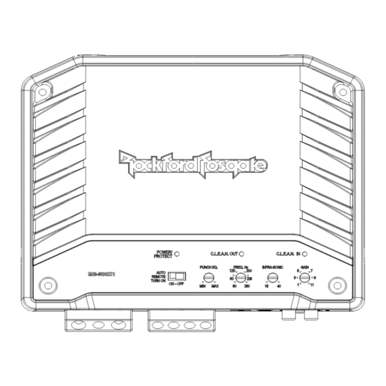
- Page 5 Dimensions 1.49” 38mm 1.97” 50mm .12” .91” 23mm 1.57” .59” 15mm 40mm 1.14” 29mm NEW TECHNOLOGIES C.L.E.A.N. – Calibrated Level Eliminated Audible Noise – Auto Remote Turn ON Switch – Utilizes the DC offset of Allows for accurate setup of an amplifier’s input and output the source units front LEFT speaker to turn the amplifier ON WITHOUT the need of additional measurement devices.
-
Page 6: Design Features
Design Features Infra-Sonic Variable Crossover A 12dB filter to prevent frequencies A built-in 12dB/octave Butterworth filter with a below the audio range from being crossover point variable from 50Hz to 250Hz. All Mono applied to the sub woofer from amps (M2-500X1) utilize a 24dB/octave. the amplifier giving you better See Pg. - Page 7 Design Features Input Switch Crossover Switch Setting the switch to 5, Selectable switch for 4 or 2 lets the amp know Low-Pass (LP) or All Pass how many inputs are being (AP) or High-Pass (HP) used. Match this to the Note: All mono amps are amount of inputs in either fixed at LP.
-
Page 8: Installation
3. Route all of the RCA cables close together and away from any high current wires. 4. Use high quality Rockford Fosgate connectors for a reliable installation and to minimize signal or power loss. 5. Think before you drill! Be careful not to cut or drill into gas tanks,... -
Page 9: Wiring The System
If you do not feel comfortable with wiring your new unit, please see your 6. Prepare the Remote turn-on wire for attachment to the amplifier local Authorized Rockford Fosgate by stripping 1/2” of insulation from the end of the wire. Insert Dealer for installation. - Page 10 Installation High Level Inputs 7” 180mm Connector side PIN 2 PIN 4 PIN 1 PIN 3 FRONT REAR PIN 1 - Blue PIN 1 - White PIN 1 - Green PIN 2 - Blue/Black PIN 2 - White/Grey PIN 2 - Green/Black PIN 3 - Brown PIN 3 - Grey PIN 3 - Violet...
-
Page 11: Input Switch
Setup Setting the Crossover C.L.E.A.N. OUT Complete the following steps for each channel. Before you adjust the gain: Place the X-OVER switch in the correct position for the Make sure that the speakers are not connected to the amplifier speaker type. outputs. -
Page 12: Troubleshooting
Troubleshooting Check Amplifier if you experience Turn-on Pop. Troubleshooting NOTE: If you are having problems after installation follow the 1. Disconnect input signal to amplifier and turn amplifier on and Troubleshooting procedures below. off. Check Amplifier for proper connections. Verify that POWER light is 2. - Page 13 Some states do not allow limitations on the length of an implied warranty, so this limitation may not apply. No person is authorized to assume for Rockford Fosgate any other liability in connection with the sale of the product.
Need help?
Do you have a question about the ELEMENT READY M2-200X2 and is the answer not in the manual?
Questions and answers