Advertisement
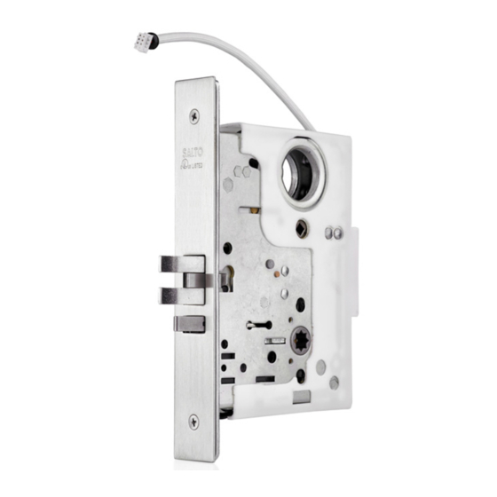
SALTO LA1T07xx/LA1T17xx mortise locks for AElement
Installation guide
Eng
Guide d'installation
F
Guía de instalación
E
LA1T17xx.. mod.
SALTO SYSTEMS, S.L.
Pol. Indust. Lanbarren, c/Arkotz, 9
20180, Oiartzun-Gipuzkoa. Spain
1121
1121-CPR-NA5003
LA1T07 / LA1T17
1 7
Electromechanical lock for fire doors
EN 14846:2008
- S 8 D - - - - -
ANSI handing code
Eng
Hand changing
Eng
1
TORX 10
7
Installation
Eng
F
Installation
PREPARING THE DOOR
Eng
1.Draw a horizontal line on edge of the door and on inside at the desired height of handle above floor.
2.Draw a vertical centre line on door edge.
3.Draw a vertical line on inside at the proper backset to align the template.
4.Mark ONLY top and bottom holes of mortise cavity (A).
Place lock face against door edge. Trace outline of faceplate as guide for faceplate routing.
5.Mortise door for lock body and faceplate.
6.Mark holes in the lateral face of the door for turnpiece (B) and
handles (C and D). Mark the holes for the corresponding electronic escutcheon fixings.
NOTE: See 3-4 pages for reader fixing holes depending on AElement model.
INSTALLING THE LOCK BODY
1.Insert wires through hole.
2.Insert the lock into the cavity.
3.Mark & drill mortise lock's fixing holes.
Fasten backplate and front plate with screws to hold lock in place.
INSTALLING THE STRIKE
1.Center strike to lock's frontplate center line.
Refer to latch to determine strike location on jamb.
Using strike as template, mark and chisel recess.
2.Drill holes for dust box. Place dust box and strike and fasten screws.
Please check that:
- Deadbolt and latch fit the cavities of the strike without touching it.
- Gap between door and jamb is 1/8".
All contents current at time of publication.
All contents current at time of publication.
SALTO Systems S.L. reserves the right to change availability of any
SALTO Systems S.L. reserves the right to change availability of any
item in this catalog, its design, construction, and/or materials.
item in this catalog, its design, construction, and/or materials.
Installation guide
1-1/16" (27)
1-1/4" (32)
LA1T17xx.. mod.
8"
(203)
ANSI code de remise
F
F
Changement de main
2
TURN 180º
GIRO 180º
GIRE 180º
Instalación
E
1-1/16"
4-3/8"
(26,5)
(110)
27/64"
2-3/4"
(10,7)
3/4"
(19)
Código mano ANSI
E
Cambio de mano
E
4
3
8
1-5/8"
5/16"
q
(41,2)
(
8)
q
6-1/8"
(156)
1-1/2"
(38,1)
(70)
LA1T07xx.. LA1T17xx..
C
L
OF
FRONTPLATE
(A)
C
L
OF
LEVER
(A)
1/4
5
6
READER
HOLES
DEPENDING
ON AELEMENT
MODEL
(B)
OF
LEVER
C
L
(D)
(C)
(D)
C
L
OF
BACKSET
221373-ED.1-31/01/2019
Advertisement
Table of Contents

Related Manuals for Salto LA1T07 Series


Summary of Contents for Salto LA1T07 Series
- Page 1 All contents current at time of publication. All contents current at time of publication. 221373-ED.1-31/01/2019 SALTO Systems S.L. reserves the right to change availability of any SALTO Systems S.L. reserves the right to change availability of any item in this catalog, its design, construction, and/or materials.
- Page 2 (cada 20000 ciclos o una vez al año), desde el exterior de la cerradura. Esto puede agregar años a la vida de la cerradura recuciendo el excesivo desgaste. En ambientes muy severos, la lubricación se debe realizar con más frecuencia. All contents current at time of publication. 221373-ED.1-31/01/2019 SALTO Systems S.L. reserves the right to change availability of any item in this catalog, its design, construction, and/or materials.
- Page 3 DOOR PREPARATION PREPARATION DE LA PORTE PREPARACIÓN DE PUERTA INFORMATIVE ONLY! SEULEMENT INFORMATIVE! ¡SOLAMENTE INFORMATIVO! 4-3/8" (110) Vertical center line of Door 2-3/4" (70) Centre vertical de l´axe Centro de la 1-3/8" (35) puerta 5/32" (4) 1-11/32" (34) OUTSIDE ONLY Reader hole EXTÉRIEUR SEULEMENT Trou de lecteur...
- Page 4 DOOR PREPARATION PREPARATION DE LA PORTE PREPARACIÓN DE PUERTA INFORMATIVE ONLY! SEUELEMENT INFORMATIVE! ¡SOLAMENTE INFORMATIVO! 4-5/8" (117,5) 2-3/4" (70) 15/64" (6) Vertical center line of Door Centre vertical de l´axe Centro de la puerta INSIDE ONLY Depth: lock center +1/4" ( +6mm ) INTÉRIEUR SEULEMENT Profondeur: centre de la serrure + 1/4"...
Need help?
Do you have a question about the LA1T07 Series and is the answer not in the manual?
Questions and answers