Table of Contents
Advertisement
Quick Links
Advertisement
Table of Contents

Related Manuals for Hali-Brite HBM 150/2 L-801A


Summary of Contents for Hali-Brite HBM 150/2 L-801A
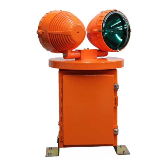
- Page 1 Installation and Maintenance Manual HBM 150/2 L-801A Airport Rotating Beacon ® Hali-Brite Inc. 1119 Madison St Brainerd, MN 56401 Tel: 800.553.6269 Fax: 218.454.0972 www.halibrite.com ® Copyright © 2020 Hali-Brite Inc., Brainerd, MN, U.S.A. Printed in U.S.A. Rev. 10...
-
Page 2: Table Of Contents
Table of Contents Introduction ......................... 3 About this Manual....................3 Model Configurations ..................3 Warranty ......................3 Disclaimers ......................4 Safety Precautions ....................... 5 Safety Statements ....................5 General Practices ....................5 Electrical Practices ....................6 Qualified Personnel ..................... 7 Proper Usage ....................... -
Page 3: Introduction
Hali-Brite further reserves the right to require the return of such goods to establish any claim. Hali-Brite’s obligation under this guarantee is limited to making repair or replacement within a reasonable time after receipt of such written notice and does not include any other costs such as... -
Page 4: Disclaimers
® If further information is required, Hali-Brite Inc. should be contacted. Sale of the product shown in this manual is subject to Hali-Brite’s terms and conditions ® including, but not limited to, the Hali-Brite Warranty. Such terms and conditions are available upon request. -
Page 5: Safety Precautions
2 Safety Precautions To help you install and maintain this equipment safely and efficiently make sure you read and understand all safety information in this manual prior to performing any procedure. Failure to do so may result in personal injury, property damage, or possible death. -
Page 6: Electrical Practices
Do not modify this equipment as this could create a safety hazard and void your ® Hali-Brite warranty. • ® Use only Hali-Brite replacement parts. • Read and carefully follow the instructions given throughout this manual for performing specific tasks and working with specific equipment. •... -
Page 7: Qualified Personnel
Do not make any modifications that have not been recommended by Hali- ® Brite • ® Do not use any replacement parts that are not purchased from Hali-Brite • ® Hali-Brite cannot be responsible for injuries or damages resulting from nonstandard, unintended applications of its equipment. -
Page 8: Specifications
3 Specifications 3.1 Electrical and Optical Specifications FAA Type ............L-801A Input Voltage..........120 or 220-240VAC, +/-10%, 50/60 Power Consumption........395W (Class I), 795W (Class II) Lenses............One clear, one green Lamps.............150W Metal Halide, Pulse Start Rated Average Lamp Life ....12,000 hours Beam Intensity ........25,000 min. effective candelas from +1°... -
Page 9: Installation
4 Installation WARNING: Allow only qualified personnel to perform the following tasks. Observe and follow the safety instructions in this document and all other related documentation. 4.1 Unpacking Handle equipment very carefully to prevent component damage. Note any exterior damage to the carton/crate that might lead to detection of equipment damage. - Page 10 Determine the beacon mounting location, and drill four ½” holes in the platform, spaced as shown in Figure 1. Figure 1 If the surface is not level, spacers or shims will be needed. Place a level on top of the weather cap and use shims as necessary under the four corners to bring the beacon to level.
- Page 11 To install power cord, perform the following procedure: 1. Unscrew the two door latches and open the chassis door. 2. Route the cable through the hole in the bottom of the chassis. Install a ½” liquid-tight conduit fitting in the chassis hole. 3.
-
Page 12: Maintenance
5 Maintenance 5.1 Maintenance Schedule Interval Task Daily Inspect for lamp failure and proper rotation. Bi-monthly Inspect cleanliness of glass. Clean as necessary. Annually Inspect all electrical connections. Replace beacon lamps at 12,000 hours. 5.2 Maintenance Procedures 5.2.1 Lamp Replacement WARNING: The lens temperature can be as high as 373 °F (189 °C). - Page 13 2. Locate the beam elevation label on the top inside edge of the head, near the edge of the reflector. 3. Loosen the two #10 Phillips-head screws located at the left and right outside edge of the head. Do not loosen them more than 2 turns. 4.
-
Page 14: Repair
6 Repair 6.1 Cover Lenses Cover lenses are replaced as follows: 1. Locate the four metal clips located at the edges of the lens. 2. Remove the screw from each of the four clips. 3. Lift the lens out of the head cover. 4. -
Page 15: Lamp Ballast
6. Remove the two wires from the top of the mercotac rotary electrical connector. 7. Place the black wire on the center tab of the new mercotac rotary electrical connector, and place the white wire on the outer tab of the new mercotac rotary electrical connector. - Page 16 5. Remove the setscrews in the motor gear, and remove the gear. (NOTE: There are two setscrews in each hole.) 6. Disconnect the motor black wire from control panel. 7. Disconnect the wires from the capacitor. 8. Remove the nuts from the four motor cap screws. 9.
-
Page 17: Troubleshooting Chart, Replacement Parts And Wiring Diagrams
Beacon Troubleshooting Chart This chart will help you to locate over 99% of beacon problems. Detailed repair procedures are located in chapter 6 of this manual. If you are still unable to solve the problem, call Hali-Brite at 800-553-6269. Start Beacon rotates? - Page 18 Mercotac rotary electrical connector 4100-0000-1A HBM150 MOTOR 9 9 9 9 Airport Equipment Qualified to FAA QUALITY CONTROL, ACCEPTANCE Specification HALI-BRITE. INC. Intertek Testing Services N.A., Inc. PRODUCT: DESCRIPTION: SERIAL #: INSPECTED BY: __________________________ DATE: HBM 150/2 Installation and Maintenance Manual...
- Page 21 MERCOTAC CONNECTOR RECYCLING Thank you for returning your used Mercotac connectors for recycling and not disposing them in the trash or landfill. The used connectors will be sent to a licensed mercury recycling facility where the liquid mercury is retrieved for future use through an environmentally safe distillation process.
Need help?
Do you have a question about the HBM 150/2 L-801A and is the answer not in the manual?
Questions and answers