Sign In
Upload
Download
Table of Contents
Contents
Add to my manuals
Delete from my manuals
Share
URL of this page:
HTML Link:
Bookmark this page
Add
Manual will be automatically added to "My Manuals"
Print this page
×
Bookmark added
×
Added to my manuals
Manuals
Brands
SoundCraft Manuals
Music Mixer
Si Performer 1
User manual
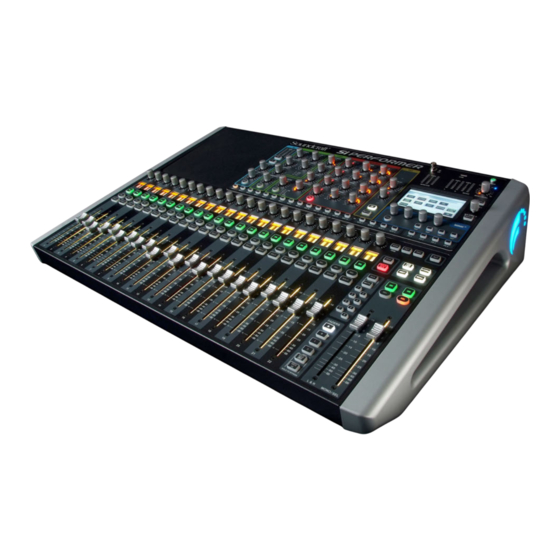
SoundCraft Si Performer 1 User Manual
Hide thumbs
1
2
Table Of Contents
3
4
5
6
7
8
9
10
11
12
13
14
15
16
17
18
19
20
21
22
23
24
25
26
27
28
29
30
31
32
33
34
35
36
37
38
39
40
41
42
43
44
45
46
47
48
49
50
51
52
53
54
55
56
57
58
59
60
61
62
63
64
65
66
67
68
69
70
71
72
73
74
75
76
77
78
79
80
81
82
83
84
85
86
87
88
89
90
91
92
93
94
95
96
97
98
99
100
101
102
103
104
105
106
107
108
109
110
111
112
113
114
115
116
117
118
119
120
121
122
123
124
125
126
127
128
129
130
131
132
133
134
135
page
of
135
Go
/
135
Contents
Table of Contents
Bookmarks
Table of Contents
Table of Contents
AN INTRODUCTION to si PERFORMER
Safety
Specifications
Getting Started
Parts Of The Console
Faderglow
Assignable Controls
Fader Layers
Control Channels
1: Control Channel Assignment
Assignable Channel Strip
Totem (Fader Follow)
Touch Screen Operation
Main Menu
Inputs & Outputs
Patching
Default Patching
2: Stageboxes
Channels & Busses
Input Channels
1: Input Setup
MIX Outputs
1: MIX Outputs Setup
Matrix Outputs
1: Matrix Outputs Setup
1: Main MIX Outputs Setup
Fx Busses
DSP Elements
Function Focus
1: Acs Input
2: Acs Gate
3: Acs Compressor
4: Acs Equaliser
5: Acs Output
Control Channel
Graphic Eq (Geq)
MIX Features
Mute Groups
Vca Groups
Copy And Paste
Audio Interrogate
Solo System
Monitoring
Clr & Alt+Clr
Shows, Cuelists, and Snapshots
Shows
Cuelist & Snapshots
1: Edit Cue
Lexicon Fx
Reverbs
1: Reverb Parameters
Delays
1: Delay Parameters
Misc Fx
1:Misc Fx Parameters
Preferences, System, Security
System Settings
1: Add/Edit User
2: Profiles
Software Updates
Reset Console
Oscillator
Appendix 01: no Sound
A Troubleshooting Guide
Advertisement
Quick Links
1
Table of Contents
2
Inputs & Outputs
Download this manual
®
User Guide
v2.0
For Soundcraft Si Performer 1, 2 & 3
Incorporating Software version 1.6
®
Table of
Contents
Previous
Page
Next
Page
1
2
3
4
5
Advertisement
Table of Contents
Need help?
Do you have a question about the Si Performer 1 and is the answer not in the manual?
Ask a question
Questions and answers
Related Manuals for SoundCraft Si Performer 1
Music Mixer SoundCraft 1601 User Manual
Soundcraft two channel battle mixer model urei 1601 user guide (44 pages)
Music Mixer SoundCraft UREI 1601E User Manual
Soundcraft user guide music mixer 1601e (56 pages)
Music Mixer SoundCraft 1603 User Manual
Soundcraft user guide music mixer 1605, 1603 (32 pages)
Music Mixer SoundCraft 1605 User Manual
Soundcraft user guide music mixer 1605, 1603 (32 pages)
Music Mixer Soundcraft UREI 1620LE User Manual
Harman (32 pages)
Music Mixer Soundcraft GIGRAC 1000st User Manual
Professional powered mixer (32 pages)
Music Mixer SOUNDCRAFT Notepad 124 FX User Manual
Soundcraft notepad mixer (44 pages)
Music Mixer SOUNDCRAFT Notepad 124 User Manual
Soundcraft notepad mixer (44 pages)
Music Mixer SOUNDCRAFT POWERSTATION 1200 User Manual
Spirit powerstation mixer (21 pages)
Music Mixer SOUNDCRAFT NOTEPAD 102 User Manual
Soundcraft notepad mixer (44 pages)
Music Mixer SoundCraft Series 10s User Manual
(59 pages)
Music Mixer SoundCraft Notepad 12FX User Manual
(44 pages)
Music Mixer SoundCraft COMPACT 4 User Manual
Soundcraft compact audio mixer (48 pages)
Music Mixer SoundCraft Si Performer User Manual
Digital live sound console (80 pages)
Music Mixer SoundCraft Si Performer Quick Start Manual
Digital live sound console (20 pages)
Music Mixer SoundCraft Si Performer 3 User Manual
(135 pages)
This manual is also suitable for:
Si performer 2
Si performer 3
Table of Contents
Print
Rename the bookmark
Delete bookmark?
Delete from my manuals?
Login
Sign In
OR
Sign in with Facebook
Sign in with Google
Upload manual
Upload from disk
Upload from URL


Need help?
Do you have a question about the Si Performer 1 and is the answer not in the manual?
Questions and answers