Table of Contents
Advertisement
Quick Links
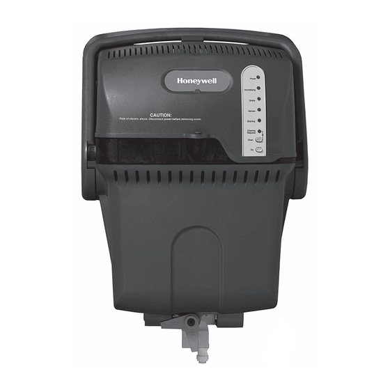
Steam Humidifier
INCLUDED IN THIS HUMIDIFIER BOX
Tools needed to install Steam Humidifier
Wire cutter/stripper
1-3/4-in. diameter hole saw
1/8-in. drill bit
Standard screwdriver
18-gauge wire (up to 5 conductor)
Torx driver T-20 and T-30
Other Requirements
Steam Humidifier flushes water at or above 140°F (60°C).
Refer to local codes for proper draining practices
for hot water.
Condensate pump rating of 212°F (100°C) if used.
Drip pan with water sensor shut-off required underneath
Steam Humidifier if installed in or above finished space.
Remote installation requires separate purchase of the
Honeywell Remote Mounting Kit (#50024917)
G
F
J
K
PROFESSIONAL INSTALLATION GUIDE
H
L
Steam Humidifier
Mounting bracket and hardware
Backflow preventer
Saddle valve
Water supply hose
E
Drain hose (10 feet)
F
Duct nozzle and gasket
G
Owner's manual
H
Service label
I
HumidiPRO Digital Control
J
Hose clamp
K
Water Hardness Test Kit
L
RO Filter System
M
*RO Tank not needed with installation
TM
E
I
M*
69-2285-11
Advertisement
Table of Contents
Troubleshooting

Related Manuals for Honeywell TrueSTEAM HM612A1000/U


Summary of Contents for Honeywell TrueSTEAM HM612A1000/U
- Page 1 Water Hardness Test Kit Drip pan with water sensor shut-off required underneath RO Filter System Steam Humidifier if installed in or above finished space. *RO Tank not needed with installation Remote installation requires separate purchase of the Honeywell Remote Mounting Kit (#50024917) 69-2285-11...
-
Page 3: Table Of Contents
NEED HELP? For assistance with this product please visit http://yourhome.honeywell.com or call Honeywell Customer Care toll-free at 1-800-468-1502. Read and save these instructions. ® U.S. Registered Trademark. Patents pending. Copyright © 2014 Honeywell International Inc. All rights reserved. Steam Humidifier System 69-2285—11... -
Page 4: Critical Installation Information
• Water test strips will be green when new. • Honeywell always recommends installing a reverse osmosis filter. Fill the plastic tube with water directly from the steam humidifier input water source. Note: It is important to test the specific input to steam humidifier, as it may differ from the faucet taps in the home. -
Page 5: Set The Automatic Flush Cycle Timing
If water hardness is in range 1: M29661 Honeywell recommends using the RO Filtration system Proceed to “Water Supply and Drain Connections” on page 14. See “Reverse Osmosis Filter” on page 25 to install the filter. For hard water without For water that is filtered through... - Page 6 Use Steam Humidifier with water that is less than 1 grain BEST per gallon hardness. A properly functioning water softener will accomplish this. PRACTICE While the steam humidifier and its available filtration options help to address the issue of water quality and hardness, homes with extreme hard water problems should consider using a whole house water softener as the primary filtration device.
-
Page 7: Proper Sizing Of A Steam Humidifier Humidifier
Proper Sizing of a Steam Humidifier The Air-Conditioning, Heating and Refrigeration Institute (AHRI) has set guidelines for determining humidification capacity requirements. The recommendation is based on the cubic footage (volume) and type of home construction – assuming typical conditions. It is important to realize many homes will have humidification requirements that differ from the guidelines depending on how the circumstances differ from standard conditions. - Page 8 Proper Sizing of a Steam Humidifier Converting square footage to cubic volume requires multiplying the square footage by the ceiling height (i.e. 2000 square foot space with 10 foot ceilings is 20,000 cubic feet). In general, the higher the ceilings, the smaller the square footage space each Steam Humidifier will cover since it must humidify the additional air volume.
-
Page 9: Steam Humidifier Pre-Install Information
In the event that a service technician needs to call in to the steam humidifier support techline, the following information is typically required for the Honeywell tech support specialist to accurately evaluate each situation. Failure to have this information ready may result in resolution delays or a potentially incomplete diagnosis. -
Page 10: Safety Definitions And Precautions
Safety Definitions and Precautions Safety Definitions These safety terms identify information you must read. CAUTION: Indicates a hazardous situation which, if not avoided, could cause bodily injury or property damage. WARNING: Indicates a hazardous situation which, if not avoided, could result in death or serious injury. Safety Precautions Make sure you read and understand the following safety hazards before installing, using, or working with the steam humidifier:... -
Page 11: Setting Homeowner Expectations
Setting Homeowner Expectations Make sure the homeowners know what to expect from their steam humidifier. Discuss the following points with the homeowners and answer any questions they have. • Achieving Humidity Setpoint. It may take up to a week of continuous operation to achieve the humidity setpoint. -
Page 12: Important Installation Requirements
Covering them can increase the temperature inside steam humidifier and shorten its life. • Do not mount directly to duct board. The remote mount nozzle attachment is allowed only with a Honeywell duct board adapter kit. See “Appendix C: Parts List” on page 67. -
Page 13: Choosing A Mounting Method
Choosing a Mounting Method Before installing steam humidifier in a home, you must decide which mounting method you want to use: Which is right for you? DUCT MOUNTING – if you can mount steam REMOTE MOUNTING – if a suitable humidifier onto the supply duct of mounting location can not be found the HVAC system:... -
Page 14: Duct Mounting
Duct Mounting Before beginning Duct Mounting: I have confirmed local codes for proper draining practices for hot water I have chosen an installation location that meets the requirements on page 10 Follow these steps to mount steam humidifier directly to the supply duct of the homeowner’s HVAC equipment. STEP ONE: Select a Mounting Location Choose a location that has access to a cold... -
Page 15: Step Three: Install Mounting Bracket To The Duct
STEP THREE: Install Mounting Bracket to the Duct Position the template on the supply duct: • Make sure the template is level and in the desired position on the duct. • Ensure proper clearances from A-coil. • Make sure the duct nozzle will have proper ”... -
Page 16: Water Supply And Drain Connections
Use clamps or ties to secure the water filter in a location that allows for removing and replacing it in the future. Honeywell recommends changing the water filter or RO canisters 1 & 2 annually, or as needed based on water conditions. -
Page 17: Step Three: Connect Steam Humidifier To The Cold Water Pipe
STEP THREE: Connect Steam Humidifier to the Cold Water Pipe Connect one end of the remaining length of water line to the backflow preventer. Apply a modest pull to ensure a tight fit. See “Reverse Osmosis Filter” on page 25 if using the Reverse Osmosis Filter. Connect the other end of this line to the saddle valve or T-fitting and manual shutoff valve. - Page 18 Water Supply and Drain Connections (continued) CAUTION EXCESSIVE SIDE LOADS ON DRAIN AND FILL HOSES CAN CAUSE LEAKS. • Allow 12 inches of drain hose and fill hose to hang free before bending • If RO Filter is installed directly below Steam unit, install to either side of drain and fill hoses.
-
Page 19: Other Plumbing Options
Other Plumbing Options The following diagrams are for applications where standard draining to a floor drain is not available.Choose the plumbing option that suits your installation. Use A, B, C, or D based on type of pipe or condensate pump. Consult and follow local plumbing codes in addition to these instructions. - Page 20 Option 2: Plumbing to a dedicated trap. 3/4 IN. MNPT X SWEAT VENTED PER 3/4 IN. FNPT X 1-1/2 IN. PVC LOCAL CODE 1-1/2 IN. (MINIMUM) PVC PIPE 1-1/2 IN. PVC ALL PLASTIC PIPE 3/4 IN. MNPT X 3/4 IN. CPVC JOINTS ARE WELDED 3/4 IN.
- Page 21 Option 4: Plumbing to sink trap. 3/4 IN. MNPT X SWEAT ALL CONNECTIONS FROM 3/4 IN. FNPT X 1-1/2 IN. PVC SOLENOID VALVE TO 1-1/2 IN. (MINIMUM) DRAIN TRAP ARE SEALED PVC PIPE 1-1/2 IN. PVC SINK 3/4 IN. MNPT X 3/4 IN. CPVC COUPLING WELD 3/4 IN.
-
Page 22: Remote Installation
If humidifier is in finished space, always install a drip pan BEST with wet switch. Honeywell recommends Diversitech WS-1 PRACTICE (wiring shown here). Remote Installation Use remote installation when no suitable duct mounting location can be found on the homeowner’s HVAC system. - Page 23 Always inspect the hose installation after at least 1 hour of BEST steam production to confirm that there are no sags in the PRACTICE hose or leaks at the connection points. Cut a slit in the insulation half way around the hose. Do not cut into the Insert the hose clamp into rubber steam hose.
-
Page 24: Proper Hose Installation
Proper Hose Installation Furnace or Mechanical Room Remote Note: If air handler location temperatures will drop below freezing at any time, Steam Humidifier must be mounted in a conditioned space, running a remote hose to the duct. Duct Mount Remote M24781 CAUTION Hot water temperature above 140°F... - Page 25 20 FT MAX WITH TRAP 2 IN. PER FT 5 FT MAX IF NO SLOPE IF NO SLOPE P - TRAP DRAIN 2 IN. PER FT TYPICAL INSTALLATION DRAIN DRAIN WHEN STEAM HUMIDIFIER 20 FT MAX P - TRAP P - TRAP IS ABOVE REMOTE NOZZLE GENTLE BEND 10 FT MAX...
- Page 26 Never support the hose by attaching it to materials that could potentially sag over time (such as PVC) or cannot support the remote hose weight. AVOID THESE COMMON MISTAKES M28672 Sharp hose bends. Horizontal run does not have minimum pitch of 2 in. per ft. Sharp hose bends.
-
Page 27: Reverse Osmosis Filter
Reverse Osmosis Filter If the steam humidifier owner’s home has water tested in range 1 on the water test strip, the Honeywell Reverse Osmosis (RO) Filtration System (HM600XROF1) should be installed in the water supply line. Failure to use the RO kit in these situations will lead to increased maintenance requirements and possible failure of the steam humidifier and its components. -
Page 28: Setting Up The Ro Filter
Setting up the RO Filter See the instruction sheet packaged with the RO Filtration System for complete installation instructions. 1. Mount the base chassis to a surface capable of holding up to 7 pounds between the home’s cold water line and the steam humidifier location. -
Page 29: Maintaining The Ro Filter
Maintaining the RO Filter Honeywell recommends the following maintenance steps be performed at least once each humidification season. Remove filters #1, #2, and #3, in this order. Reconnect filters in this order: • Empty water from the #3 filter and reconnect to the RO System. -
Page 30: Before Wiring Steam Humifier
Before Wiring Steam Humidifier Before wiring the steam humidifier: I will read the section “Understand the DIP Switches” beginning on this page I will read the section “Deciding on the Wiring Configuration” beginning on page 30 Using the DIP Switches The wiring features are configured by DIP settings, which are described under the steam humidifier cover. - Page 31 DIPS 3, 4, and 5 are used to configure the humidifier operation for your unique application. DIP 3: Used to enable wireless operation. • If DOWN (default), wireless terminal is disabled. M29610 • If UP, wireless terminal is enabled. DIP 4: Used to configure power monitoring. •...
-
Page 32: Deciding On The Wiring Configuration
Deciding on the Wiring Configuration Before making decisions about wiring configurations: I understand when to use the DIP switches and how to set them for the humidity control. Steam humidifier wiring is different from evaporative pad humidifier wiring. In addition to solenoid water valve actuation, steam humidifier can monitor system power and regulate system fan operation. - Page 33 IMPORTANT NOTE: The images below are not complete wiring diagrams. It only depicts power monitoring and is not meant to be a stand alone diagram. Please refer to the “Wiring the steam humidifier” section in the following pages for complete wiring diagrams. WIRING BASICS: CONFIGURATION 1 Thermostat with Humidity Control...
-
Page 34: Step Two: Make System Fan Regulation Decision
STEP TWO: Make System Fan Regulation Decision System Fan Regulation is a configuration that requires steam humidifier to monitor the HVAC system fan and make sure the fan is on if humidity is needed. This helps ensure that airflow will distribute humidity into the living space, and prevents water condensation in the duct. - Page 35 IMPORTANT NOTE: The images below are not complete wiring diagrams. It only depicts power monitoring and is not meant to be a stand alone diagram. Please refer to the “Wiring the steam humidifier” section in the following pages for complete wiring diagrams. WIRING BASICS: CONFIGURATION 1 Thermostat with When using a thermostat with integrated...
-
Page 36: Step Three: Make Add-On Air Proving Decision
Honeywell HIGHLY recommends adding an Add-On Air Proving Device for ALL Steam Humidifier installations. IMPORTANT NOTE: The image below is not a complete wiring diagram. It only depicts power monitoring and is not meant to be a stand alone diagram. -
Page 37: Using The Terminals
Wiring the Steam Humidifier You will need to wire steam humidifier using the diagram that applies to your humidity control. Remember to include the wiring and DIP settings required for power monitoring, system fan regulation, and add-on air proving (if used). Using the Terminals Use the terminals (found inside the cover) to wire steam humidifier to the humidity control and the... -
Page 38: Using The Correct Control Diagram
HUMIDITY BOOST Light System Auto Next Auto Make sure that the thermostat used HVAC isolates Y from G. All Honeywell Prestige, VisionPRO IAQ, VisionPRO, and Focus Pro thermostats do this. OUTDOOR SENSOR (OPTIONAL) STEAM HUMIDIFIER RECOMMENDED AIR FLOW SWITCH (AFS) - Page 39 Installing the Humidistat Remote Installation Choose a location in the living area. NOTE: Select a location clear of drafts or excessive humidity. Avoid mounting near doors or windows, or in bathrooms or kitchens. M34567 Duct-Mount Installation (recommended) 1. Choose a location on the RETURN duct. 2.
- Page 40 Installing the Humidistat Duct-Mount Installation (continued) 5. Insert the duct tube. 6. Secure the wallplate. Insert the duct tube through the wallplate before securing to the duct. M34582 Secure the wallplate to the duct with sheet metal screws (provided). M34671 7.
-
Page 41: Mounting The Outdoor Sensor
Mounting the Outdoor Sensor (Not required if window protection isn’t needed) Location Mount the sensor where: • it cannot be tampered with. • there is good air circulation. • surface is flat. • wire distance between sensor and humidistat is less than 200 feet. •... - Page 42 Wiring the Outdoor Sensor CAUTION: Electrical Interference (Noise) Hazard. Can cause erratic system operation. Keep wiring at least one foot away from large inductive loads such as motors, line starters, lighting ballasts and large power distribution panels. Use shielded cable to reduce interference when rerouting is not possible. Be sure wires have a cable separate from the thermostat cable.
- Page 43 Mount Humidity Control WALLPLATE TABS Align the 4 tabs on the wallplate with the slots on the back of the control, then push gently SLOTS ON BACK OF until the control snaps in place. HumidiPRO TABS M34583 Checkout Allow C7089B Outdoor Sensor to absorb outdoor air for a minimum of twenty minutes before taking a reading. With an accurate thermometer (±1°F [0.5°C]), measure the temperature at the sensor location, allowing time for the thermometer to stabilize before reading.
- Page 44 Advanced Installer Setup Honeywell has already programmed this control to work properly in most applications. However, you can adjust the advanced settings by following the steps below. To begin, press and hold the p and LIGHT buttons until Press p or q to change settings.
- Page 45 Honeywell HumidPRO Frost Index Outdoor Temp -10°F 0°F 10°F 20°F 30°F 40°F *Black Numbers show highest humidity allowed when Default RH% (35%) is Selected. Note: Smaller grey numbers show highest humidity allowed when Maximum RH% (60%) is selected. Installer System Test/Checkout To begin, press and hold the p and q buttons until the display changes.
-
Page 46: Startup And Checkout
Startup and Checkout When installation is complete, plug steam humidifier in and turn the humidity control on. Make sure it is running properly before turning the system over to the homeowner. Once steam humidifier is running, day-to-day operation is hands-free, except for occasional cleaning. The homeowner can use the control to adjust the humidity setpoint, adjust the frost setting (if used), or turn steam humidifier off as desired. -
Page 47: Routine Maintenance
At the end of the cycle, steam humidifier refills the tank with fresh water and automatically returns to normal operation. Manual Cleaning Cycle Honeywell recommends that steam humidifier be manually cleaned and the water filter be changed at least once each humidification season. The manual cleaning is necessary to remove solid mineral deposits left behind during operation. - Page 48 BEST Perform all cleaning steps at least once per humidification season. PRACTICE CAUTION: Scalding hazard. • If you override the cooling action of the flush cycle, the tank will empty immediately, regardless of water temperature. Make sure the drain can handle up to 212°F (100°C) if you do this.
-
Page 49: Step Two: Remove The Water Tank
CAUTION: Scalding hazard. Do not attempt to remove steam humidifier from the mounting bracket during operation or when the tank is full of water. The heating element could be hot when tank is removed. Failure to comply could result in severe scalding. STEP TWO: Remove the Water Tank Make sure the tank is empty. -
Page 50: Step Three: Clean The Tank
STEP THREE: Clean the Tank Use tap water to flush loose minerals from the tank: • Sediment screen at tank’s bottom is removable. • For a more thorough cleaning, soak tank in water with CLR , LimeAway or white vinegar. Then ®... -
Page 51: Water Level Sensor Troubleshooting Steps
Water Level Sensor Troubleshooting Steps WARNING: Electrocution Hazard. This test should be done when current is not present on pins. Always unplug the humidifier before testing. Test Setup Good Water Sensor • Remove and drain the tank. The tank must be The water sensor is good if all pins show an open- empty. -
Page 52: Step Five: Reinstall The Tank
STEP FIVE: Reinstall the Tank Before reinstalling the tank and cover, perform these checks: • Clear any dust from the ventilation holes in the cover. • Clear any debris from the water drain tube. • Make sure the water tank gasket seal is seated properly in the steam humidifier base. -
Page 53: Troubleshooting
Troubleshooting Steam Humidifier has internal system diagnostics that monitor operation, maintenance schedules, and faults. If a system fault is detected, Steam Humidifier will attempt to recover up to five times in a 24-hour period. • If Steam Humidifier is unable to recover by itself within 24 hours, the red Service light blinks in a series that indicates the fault detected. - Page 54 No. of Fault Description Auto-Recoverable? Steps to Fix Service LED (Performed Only By Professional HVAC Technician) Blinks Heating element If this is a new install: 1. Reset the error code and power cycle the unit. overheated. 2. If the error code comes back, replace the unit. If this is NOT a new install: 1.
- Page 55 No. of Fault Description Auto-Recoverable? Steps to Fix Service LED (Performed Only By Professional HVAC Technician) Blinks HVAC power Yes, system will 1. Ensure HVAC equipment has power. not present. return to “Ready” 2. Check circuit breaker or replace fuse if circuit is tripped. if fault no longer 3.
- Page 56 No. of Fault Description Auto-Recoverable? Steps to Fix Service LED (Performed Only By Professional HVAC Technician) Blinks Tank failed to drain. CAUTION: Water in tank may be hot (>140°F [60°C]). 1. Press the Drain button. 2. If tank fails to drain, turn humidistat/thermostat off and wait for water in tank to cool.
-
Page 57: A: Specifications
A: Specifications Humidifying Capacity Electrical Ratings and Tolerances HM609: up to 9 gpd (34 lpd) Input Ratings HM612: up to 12 gpd (45 lpd) • Power Supply: 120VAC +10-15%, 60Hz - HM609: 1200W at 120VAC at full load Humidified Area - HM612: 1440W at 120VAC at full load HM609: 8,000–18,400 cubic feet •... -
Page 58: B: Advanced Steam Humififier Wiring
HUMIDITY BOOST Light System Auto Next Auto HVAC Make sure that the thermostat used isolates Y from G. All Honeywell Prestige, OUTDOOR VisionPRO IAQ, VisionPRO, and Focus Pro SENSOR (OPTIONAL) STEAM HUMIDIFIER thermostats do this. RECOMMENDED AIR FLOW SWITCH (AFS) - Page 59 B: Advanced Steam Humidifier Wiring OPTION 3: VisionPRO IAQ Wiring with Fan Delay • Follow this diagram if you are using VisionPRO IAQ with Steam Humidifier’s fan-delay feature. • The system fan will turn on when the water temperature reaches 176°F (80°C). •...
- Page 60 B: Advanced Steam Humidifier Wiring OPTION 5: Prestige IAQ with fan delay • Follow this diagram if you are using Prestige IAQ with Steam Humidifier’s fan-delay feature. • The system fan will turn on when the water temperature reaches 176°F (80°C). THX9421R Furnace Steam Humidifier...
- Page 61 B: Advanced Steam Humidifier Wiring OPTION 6: Prestige IAQ or All New VisionPRO without fan delay • Follow this diagram if you are using Prestige IAQ to turn system fan on immediately with humidity call. THX9421R FURNACE STEAM HUMIDIFIER THM5421R PRESTIGE IAQ AND STEAM HUMIDIFIER WITHOUT FAN DELAY M32919B Steam Humidifier System 69-2285—11...
- Page 62 B: Advanced Steam Humidifier Wiring OPTION 7: Wiring Steam Humidifier with zoning W1/E Humidistat Equipment Furnace DS/BK HZ432 (AFS Monitor Recommended) Steam Humidifier Alternative (Power Monitor Setting) M32920A OPTION 8: Wiring Prestige or All New VisionPRO with wireless Steam Humidifier THM4000R1000 THX9321R SUBBASE...
- Page 63 B: Advanced Steam Humidifier Wiring OPTION 9: Prestige IAQ or All New VisionPRO controlling Steam Humidifier with zoning with fan delay (recommended) THX9421R HZ432 FURNACE STEAM THM5421R HUMIDIFIER AFS MONITOR RECOMMENDED M33055B Steam Humidifier System 69-2285—11...
- Page 64 B: Advanced Steam Humidifier Wiring OPTION 10: Steam Humidifier wired to a dedicated fan/blower STEAM HUMIDIFIER TrueIAQ TRANSFORMER R8222 (120 VOLT HOT) (120 VOLT COMMON) M33056 (AFS Monitor Recommended) Alternative (Power Monitor Setting) M32922A ISU 25 must be set to 3 Steam Humidifier System 69-2285—11...
- Page 65 B: Advanced Steam Humidifier Wiring OPTION 11: Prestige IAQ or All New VisionPRO controlling Redlink wireless Steam Humidifier with zoning NOTE: To get air humidity to all zones in idle mode you would need to jump the G on all zones being used and verify that the thermostat does not have a Y/G interconnect.
- Page 66 B: Advanced Steam Humidifier Wiring OPTION 12: VisionPRO IAQ controlling 2 Steam Humidifiers COMMUNICATION LED COMMUNICATION TERMINALS TH9421C1004 24 VAC THM5421C1008 FURNACE AFS Monitor Recommended M32914A STEAM HUMIDIFIER 1 STEAM HUMIDIFIER 2 THE YTH9421C1002 KIT INCLUDES THE TH9421C1004 VISION-PRO IAQ THERMOSTAT AND THE THM5421C1008 EQUIPMENT INTERFACE MODULE.
- Page 67 B: Advanced Steam Humidifier Wiring OPTION 13: Prestige IAQ controlling 2 Steam Humidifiers THX9421R5005 THM5421R1005 FURNACE DEVICE SENSOR TYPE STEAM STEAM AFS MONITOR RECOMMENDED HUMIDIFIER 1 HUMIDIFIER 2 A DOUBLE-POLE RELAY SUCH AS THE R8228D1018 IS REQUIRED. AN AIR-FLOW SWITCH IS RECOMMENDED. IF AN AIR FLOW SWITCH IS NOT USED THERE DOES NOT NEED TO BE A WIRE ATTACHED TO C ON THE STEAM HUMIDIFIER AND THE #4 DIPSWITCH NEEDS TO BE SET TO “ON”.
- Page 68 B: Advanced Steam Humidifier Wiring OPTION 14: Steam Humidifier wired to equipment with powered terminals with Steam Humidifier controlling the fan 24 V 24 V AIR-FLOW SWITCH STEAM HUMIDIFIER HUM W2 Y1 DHUM G COM W/W1 Y/Y2 FURNACE TERMINALS NOTES: YOU MUST ADD A 24VAC ISOLATION RELAY BETWEEN THE STEAM HUMIDIFIER AND THE AIR HANDLER.
-
Page 69: C: Parts List
C: Parts List Figure Part Number Part Description Reference 50024917-001 Remote Mounting Kit (with 10-foot hose) 50024917-002 Remote Mounting Kit (with 20-foot hose) 50028004-001 Cover 50028003-001 Duct Nozzle 50028001-001 Remote Nozzles 50020012-001 Mounting Bracket 50027997-001 Solenoid Valve 50033181-001 9/12 Gallon Tank and Gasket Kit 50027998-002 Water Level Sensor Assembly 32001616-001... - Page 72 Automation and Control Solutions Honeywell International Inc. 1985 Douglas Drive North Golden Valley, MN 55422 http://customer.honeywell.com ® U.S. Registered Trademark. © 2016 Honeywell International Inc. 69-2285—11 M.S. Rev. 01-16 Printed in U.S.A.
Need help?
Do you have a question about the TrueSTEAM HM612A1000/U and is the answer not in the manual?
Questions and answers