
Related Manuals for nvent G280648G Series


Summary of Contents for nvent G280648G Series
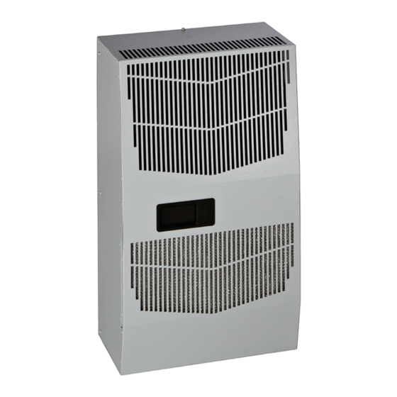
- Page 1 SpectraCool Air Conditioner G28 48 VdC 2-StAGe Model INSTRUCTION MANUAL Rev. C © 2020 nVent 89174770 P/N 89174570...
-
Page 2: Table Of Contents
F-GAS INFORMATION ..................................17 NOTE: Some of the information in this manual may not apply if a special unit was ordered. If additional drawings for a special unit are necessary, they have been inserted. Contact nVent Equipment Protection if further information is required. -
Page 3: Handling & Testing The Air Conditioner
Save the packing material and request an inspection. Then file a claim with the delivering carrier within 15 days of delivery. nVent Equipment Protection cannot accept responsibility for freight damages; however, we will assist you in any way possible. -
Page 4: Installation Instructions
5. Refer to the nameplate for electrical requirements. Wire the unit to a properly grounded power supply. Electrical circuit should be fused with slow blow or HACR circuit breaker. 6. Set thermostat for required cabinet temperature. Refer to on page 6 for thermostat adjustment & operation. DIMENSIONAL DRAWING © 2020 nVent 89174770 - 4 -... - Page 5 28-1000-13 SURFACE MOUNT Figure 1 Cutout Dimensions © 2020 nVent 89174770 - 5 -...
-
Page 6: Technical Information
86.7 -26.1 29.4 -23.3 32.2 -20.6 113.3 -17.8 37.8 40.6 -12.2 43.3 146.7 -9.4 46.1 157.5 -6.7 18.5 48.9 -3.9 51.7 -1.1 54.4 197.5 57.2 213.3 62.8 246.7 45.5 65.6 263.8 12.8 51.5 © 2020 nVent 89174770 - 6 -... -
Page 7: Performance Data
External Airflow (CFM) Variable, 300 max Hose discharge/Optional Condensate Management powered C/E Electrical Data Rated Voltage (VDC) Rated Frequency Voltage Range 39-57 Cooling Amps at Max Conditions 17.7 Evaporator Fan RLA Condenser Fan RLA © 2020 nVent 89174770 - 7 -... -
Page 8: Wire Diagrams
WIRE DIAGRAMS G280648GXXX GENERIC WIRE DIAGRAM (ACTUAL UNIT OPTIONS MAY VARY) © 2020 nVent 89174770 - 8 -... -
Page 9: Maintenance
The condenser blower is mounted on its own bulkhead and is easily accessible by removing the front cover. Caution! Operation of the air conditioner in areas containing airborne caustics or chemicals can rapidly deteriorate filters, condenser coils, blowers and motors, etc. Contact nVent for special recommendations. © 2020 nVent 89174770... -
Page 10: Refrigerant Loss
Controller 89174555 Filter, Air, Reusable 89119662 Filter/Dryer 52-6028-00 Heater, Compressor or Condenser Pan (optional) 10-1030-08 Thermistor 89075654 Impeller, Condenser 89102441 Impeller, Evaporator 89102440 Fuse, Controller 89085114 Condenser Impeller Controller 89122338 Relay, Compressor 10-1005-22 © 2020 nVent 89174770 - 10 -... -
Page 11: Remote Access Control
Evaporator Fan On Start-up Request AMBER Not Used Not Used AMBER Not Used Not Used AMBER Heater Active Not Used Alarm Active Not Used AMBER Controller Active Not Used AMBER Not Used Not Used © 2020 nVent 89174770 - 11 -... -
Page 12: Displaying And Changing Program Variables
The Remote Access Control has a normally closed dry contact alarm output with a resistive load rating of 250 VAC at 3 amps. Two yellow 18 AWG wires located at the back of the air conditioner provide a connection to this output. © 2020 nVent 89174770 - 12 -... -
Page 13: Alarm Input Connection
Read and change the state of IP addressing (static or dynamic) • Read current Alarm Status SOFTWARE AND CONFIGURATION FILE DOWNLOADS The PC Interface Tool, MIB file, EDS file, EtherNet_IP Object file and Coil_Register file can be downloaded from www.nVent.com/HOFFMAN © 2020 nVent 89174770 - 13 -... -
Page 14: Using The Pc Interface Tool
• Select the Settings tab • Select the value to change • Make the change to the value • Select the Change Setting button • Change can be verified in ACU Values tab © 2020 nVent 89174770 - 14 -... -
Page 15: Remote Access Control Pin-Out
ID GND Y (na) U2 INPUTS GND (na) T1, EVAP IN THERMISTOR T2, EVAP OUT THERMISTOR T1, T2 GND CONTROLLER POWER BLK40 CONTROLLER POWER WHT41 POWER GROUND BLACK U3 DATA DIRECTION GREEN DATA WHITE © 2020 nVent 89174770 - 15 -... -
Page 16: Trouble Shooting
7. Make sure the coils are clean. Then check evaporator “air in” and “air out” temperatures. If the temperatures are the same: • Possible loss of refrigerant Repair or Replace • Possible bad valves in the defective part compressor © 2020 nVent 89174770 - 16 -... -
Page 17: Symptoms And Possible Causes
Unit blows breakers Short in system Drain plugged Drain tube kinked Getting water in enclosure Enclosure not sealed (allowing humidity in) Mounting gasket damaged For additional technical support, contact nVent Equipment Protection at 800-896-2665. F-GAS INFORMATION G280648GXXX Refrigerant Kühlmittel R134a Chłodziwo... - Page 18 NOTES © 2020 nVent 89174770 - 18 -...
- Page 19 NOTES © 2020 nVent 89174770 - 19 -...
- Page 20 Rev. C © 2020 nVent 89174770 P/N 89174570...
Need help?
Do you have a question about the G280648G Series and is the answer not in the manual?
Questions and answers