
Related Manuals for nvent SPECTRACOOL G280626G160B


Summary of Contents for nvent SPECTRACOOL G280626G160B
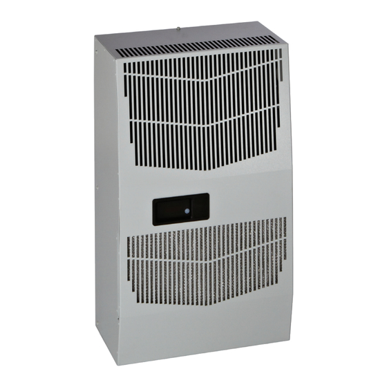
- Page 1 SPECTRACOOL Air Conditioner G280626G160B Model INSTRUCTION MANUAL Rev. C © 2019 nVent 89171774 P/N 89171774...
-
Page 2: Table Of Contents
BASIC AIR CONDITIONING TROUBLE SHOOTING CHECK LIST - REMOTE ACCESS CONTROL VERSION ..........20 Symptoms and Possible Causes - Remote Access Control Version ........................... 22 F-GAS INFORMATION ......................................22 WARRANTY AND RETURN POLICY https://hoffman.nvent.com/en/hoffman/warranty-information © 2019 nVent 89171774 - 2 -... -
Page 3: Receiving The Air Conditioner
Damage evident upon receipt should be noted on the freight bill. Damage should be brought to the attention of the delivering carrier -- NOT to nVent Equipment Protection -- within 15 days of delivery. Save the carton and packing material and request an inspection. Then file a claim with the delivering carrier. -
Page 4: Technical Information
Unit is set at the factory, no adjustment necessary. At a saturated condenser temperature of 85 F (95 psig), the condenser fans will power off. At a saturated condenser temperature of 118 F (165 psig), the condenser fans will power on. © 2019 nVent 89171774 - 4 -... -
Page 5: Remote Access Control
AMBER Compressor On — AMBER Evaporator Fan On Start-up Request AMBER Not Used — AMBER Not Used — AMBER Heater Active — Alarm Active — AMBER Controller Active — AMBER Not Used — © 2019 nVent 89171774 - 5 -... -
Page 6: Displaying And Changing Program Variables
The Remote Access Control has a normally open dry contact alarm output with a resistive load rating of 250 VAC at 3 amps. Two yellow 18 AWG wires located at the back of the air conditioner provide a connection to this output. © 2019 nVent 89171774 - 6 -... -
Page 7: Alarm Input Connection
Read and change Gateway IP Address, Device IP Address, Subnet Mask, Trap IP Address and Community • Read and change Unit Identification • Read and change the state of IP addressing (static or dynamic) • Read current Alarm Status © 2019 nVent 89171774 - 7 -... -
Page 8: Using The Pc Interface Tool
SOFTWARE AND CONFIGURATION FILE DOWNLOADS The PC Interface Tool, MIB file, EDS file, EtherNet_IP Object file, Coil_Register file and GSDML file can be downloaded from https://lp.hoffman1.nvent.com/remote-access-control-support-center. USING THE PC INTERFACE TOOL The PC Interface Windows Application gives the user the ability to communicate with the air conditioner unit to read/write parameters using either Ethernet or USB connections. -
Page 9: Ethernet Communication Mode
Enter the desired Device IP Address, Subnet MASK, Gateway IP, and Trap IP. Change the Community string to private if it has not yet been changed. • Click the Reprogram ACU button to write and save the new static IP information to the Commboard or RAC module © 2019 nVent 89171774 - 9 -... -
Page 10: Remote Access Control Pin-Out
ID GND Y (na) U2 INPUTS GND (na) T1, EVAP IN THERMISTOR T2, EVAP OUT THERMISTOR T1, T2 GND CONTROLLER POWER BLK40 CONTROLLER POWER WHT41 POWER GROUND BLACK U3 DATA DIRECTION GREEN DATA WHITE © 2019 nVent 89171774 - 10 -... -
Page 11: Schematics And Wiring Diagrams For Remote Access Control
SCHEMATICS AND WIRING DIAGRAMS FOR REMOTE ACCESS CONTROL 6000 BTU 1-PHASE SCHEMATIC (ACTUAL UNIT OPTIONS MAY VARY) 89084977Q Rev. A © 2019 nVent 89171774 - 11 -... -
Page 12: 6000 Btu 1-Phase Wire Diagram For Remote Access Control (Actual Unit Options May Vary)
6000 BTU 1-PHASE WIRE DIAGRAM FOR REMOTE ACCESS CONTROL (ACTUAL UNIT OPTIONS MAY VARY) 89165274 REV. B © 2019 nVent 89171774 - 12 -... -
Page 13: Dimensional Drawings
ALUMINUM INLET FILTER REMOVAL ON SIDE 1.26 14.00 FRONT VIEW SIDE VIEW 1/4-20 UNC (11X) 31.9 355.6 MOUNTING HOLES 15.26 387.6 BACK VIEW ACCESS HOLE TO .375 O.D. DRAIN STUB (CONTROLLER DEPTH) BOTTOM VIEW 21.1 © 2019 nVent 89171774 - 13 -... -
Page 14: Installation Instructions With Remote Access Control
Electrical circuit should be fused with slow blow or HACR circuit breaker. 7. Set controller setpoints for required cabinet temperature. Refer to DISPLAYING AND CHANGING PROGRAM VARIABLES on page 6 for setpoint adjustment and operation. 28100013 Figure 1 Cut-out Drawing © 2019 nVent 89171774 - 14 -... -
Page 15: Maintenance
1. Flush the filter with warm water from the exhaust side to the intake side. DO NOT USE CAUSTICS. 2. After flushing, allow filter to drain. Placing it with a corner down will assure complete drainage. © 2019 nVent 89171774... -
Page 16: Condenser And Evaporator Air Movers
CAUTION Operation of the air conditioner in areas containing airborne caustics or chemicals can rapidly deteriorate filters, condenser coils, blowers and motors, etc. Contact nVent Equipment Protection for special recommendations. REFRIGERANT LOSS Each air conditioner is thoroughly tested prior to leaving the factory to insure against refrigeration leaks. Shipping damage or microscopic leaks not found with sensitive electronic refrigerant leak detection equipment during manufacture may require repair or recharging of the system. -
Page 17: Refrigerant Properties Chart (R 407C)
88.7 70.7 62.8 410.7 375.9 97.8 78.8 65.6 436.5 401.7 12.8 107.5 87.5 FUNCTIONAL DATA Evaporator. Air Condenser Evaporator Unit Amps(A) In(°F) Delta(°F) Delta(°F) 65-80 2.5-3.9 25-33 19-29 G280626GXXX 80-100 2.9-4.6 27-38 23-33 © 2019 nVent 89171774 - 17 -... -
Page 18: 4000/6000 Btu Unit Characteristics
Rated Voltage (50/60 Hz) 230V Rated Frequency 50/60 Hz Voltage Range +/- 10% of rated Cooling Amps at Max Conditions 4.6/5.8 Heating Amps Compressor RLA / LRA 2.6/17.7 Evaporator Fan RLA* Condenser Fan RLA* © 2019 nVent 89171774 - 18 -... -
Page 19: Service Data
Head Pressure Control Switch 89083015 Heater, 2000 Watt 10-1038-54 Impeller Condenser 10-1091-124 Impeller Evaporator 10-1091-122 Limit Switch (automatic) 10-1033-01 Limit Switch (manual) 10-1033-07 Relay, Compressor Start 10-1042-13 Thermal Expansion Valve 89057143 Thermal Overload, Compressor MRA5742-114 © 2019 nVent 89171774 - 19 -... -
Page 20: Basic Air Conditioning Trouble Shooting Check List - Remote Access Control Version
Restart Time Delay mode. Within 3 minutes, symbol 1 should display without flashing. Is symbol 1 displayed without flashing? YES, proceed to step 6. NO, possible problem: » Unit still in Recycle Time Delay mode Wait and/or heat » Enclosure temperature below cooling enclosure thermistor T1 setpoint temperature © 2019 nVent 89171774 - 20 -... - Page 21 8. Make sure the coils are clean then check the evaporator “air in” and “air out” temperatures. If the temperatures are the same: » Possible loss of refrigerant Repair or Replace defective part » Possible bad valves in compressor © 2019 nVent 89171774 - 21 -...
-
Page 22: Symptoms And Possible Causes - Remote Access Control Version
Unit blows breakers Short in system Drain plugged Drain tube kinked Getting water in enclosure Enclosure not sealed (allowing humidity in) Mounting gasket damaged For additional technical support, contact NVent Equipment Protection at 800-896-2665. F-GAS INFORMATION G280626GXXX Refrigerant Kühlmittel R407C Chłodziwo... - Page 23 NOTES © 2019 nVent 89171774 - 23 -...
- Page 24 Rev. C © 2019 nVent 89171774 P/N 89171774...
Need help?
Do you have a question about the SPECTRACOOL G280626G160B and is the answer not in the manual?
Questions and answers