Table of Contents
Advertisement
Quick Links
www.ti.com
EVM User's Guide: BQ25185EVM
BQ25185 Evaluation Module
Description
The BQ25185 evaluation model (EVM) is designed
to evaluate and test various operating modes
of the BQ25185. The EVM is designed for a
complete test friendly evaluation with visual indicators.
The BQ25185 is an integrated battery charge
management IC that integrates most common
functions for solar based industrial devices with
rechargeable batteries: linear charging, regulated
output, Factory mode, and battery tracking VINDPM.
SLUUCS1 – OCTOBER 2023
Submit Document Feedback
Features
•
•
•
•
•
•
•
•
•
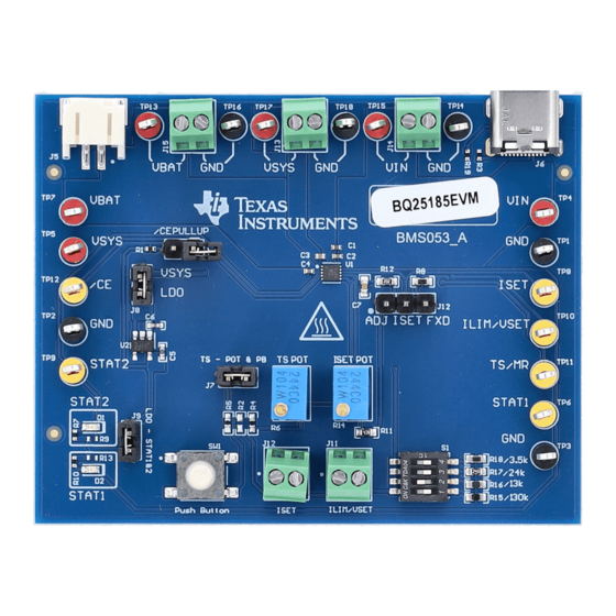
Figure 1-1. BQ25185EVM Hardware Board
Caution
Copyright © 2023 Texas Instruments Incorporated
1-A linear battery charger
Resistor configurable battery regulation voltage
with 0.5% accuracy
Thermal charging profile with configurable Hot,
and Cold thresholds
Power Path management for powering the system
and charging the battery
4-uA Factory mode for maximizing battery shelf life
Resistor programmable pins VSET/ILIM and ISET
Status Pins, STAT1 and STAT2 to show device
status
Test points for easy probing
On-board resistances for minimal test setup
Caution hot surface
Contact can cause burns
Do not touch!
Some components may reach high temperatures >55°C when the board
is powered on. The user must not touch the board at any point during
operation or immediately after operating, as high temperatures may be
present.
Description
BQ25185 Evaluation Module
1
Advertisement
Table of Contents

Related Manuals for Texas Instruments BQ25185EVM


Summary of Contents for Texas Instruments BQ25185EVM
- Page 1 • Test points for easy probing • On-board resistances for minimal test setup Figure 1-1. BQ25185EVM Hardware Board Caution hot surface Contact can cause burns Do not touch! Caution Some components may reach high temperatures >55°C when the board is powered on.
-
Page 2: Kit Contents
The BQ25185EVM can be evaluated using a micro-USB input and a battery with a 2-pin JST connector. The EVM contains pin headers are provided to connect with power supplies to simulate charging operation. With on-board potentiometers, jumpers, switches, and terminal blocks, different battery charger parameters can be configured. -
Page 3: Evm Connectors And Test Points
Table 2-3. Test Point Descriptions Test Point Description TP1, TP2, TP3, TP14, TP16, TP18 IC GND test point SLUUCS1 – OCTOBER 2023 BQ25185 Evaluation Module Submit Document Feedback Copyright © 2023 Texas Instruments Incorporated... -
Page 4: Testing Procedures
Channel 3 (SC #3) will be used to probe VSYS 3.2 Charge Mode Connect the equipment as follows: • Power Supply PS #1: VIN of the BQ25185EVM at 5 V • Power Supply PS #2: VBAT of the BQ25185EVM at 3.7 V •... - Page 5 To enter the Factory Mode state, connect the equipment as follows: • Power Supply PS#1: VIN for the BQ25185EVM at 5V • Power Supply PS #2: VBAT of the BQ25185EVM at 3.7 V • Scope Channel SC #1: VIN at TP4 •...
- Page 6 Hardware Design Files www.ti.com Figure 3-1. Enter Factory Mode on VIN removal Figure 3-2. Exit Factory Mode with VIN insertion 4 Hardware Design Files BQ25185 Evaluation Module SLUUCS1 – OCTOBER 2023 Submit Document Feedback Copyright © 2023 Texas Instruments Incorporated...
- Page 7 Hardware Design Files 4.1 Schematics Figure 4-1. BQ25185EVM Schematic SLUUCS1 – OCTOBER 2023 BQ25185 Evaluation Module Submit Document Feedback Copyright © 2023 Texas Instruments Incorporated...
- Page 8 Figure 4-3. Top Solder Figure 4-2. Top Overlay Figure 4-4. Top Layer Figure 4-5. Bottom Layer Figure 4-7. Bottom Overlay Figure 4-6. Bottom Solder BQ25185 Evaluation Module SLUUCS1 – OCTOBER 2023 Submit Document Feedback Copyright © 2023 Texas Instruments Incorporated...
- Page 9 Hardware Design Files Figure 4-8. Board Dimensions SLUUCS1 – OCTOBER 2023 BQ25185 Evaluation Module Submit Document Feedback Copyright © 2023 Texas Instruments Incorporated...
- Page 10 PCB Label 0.650 x 0.200 LBL1 THT-14-423-10 Brady W x 0.200" H - 10,000 per inch roll RES, 10.0 k, 1%, 0.063 10.0k RC0402FR-0710KL Yageo America W, 0402 BQ25185 Evaluation Module SLUUCS1 – OCTOBER 2023 Submit Document Feedback Copyright © 2023 Texas Instruments Incorporated...
- Page 11 SH-JP1, SH-JP2, SH- Shunt, 100mil, Gold Shunt SNT-100-BK-G Samtec JP3, SH-JP4 plated, Black Tactile Switch SPST-NO Top Actuated Surface SMT_TACT 4.30152E+11 Wurth Electronics Mount SLUUCS1 – OCTOBER 2023 BQ25185 Evaluation Module Submit Document Feedback Copyright © 2023 Texas Instruments Incorporated...
- Page 12 RES, 100 k, 1%, 0.0625 100k W, AEC-Q200 Grade 0, AC0402FR-07100KL Yageo America 0402 RES, 10.0 k, 1%, 0.063 R9, R13 10.0k RC0402FR-0710KL Yageo America W, 0402 BQ25185 Evaluation Module SLUUCS1 – OCTOBER 2023 Submit Document Feedback Copyright © 2023 Texas Instruments Incorporated...
-
Page 13: Additional Information
6 Revision History NOTE: Page numbers for previous revisions may differ from page numbers in the current version. DATE REVISION NOTES October 2023 Initial Release SLUUCS1 – OCTOBER 2023 BQ25185 Evaluation Module Submit Document Feedback Copyright © 2023 Texas Instruments Incorporated... - Page 14 STANDARD TERMS FOR EVALUATION MODULES Delivery: TI delivers TI evaluation boards, kits, or modules, including any accompanying demonstration software, components, and/or documentation which may be provided together or separately (collectively, an “EVM” or “EVMs”) to the User (“User”) in accordance with the terms set forth herein.
- Page 15 www.ti.com Regulatory Notices: 3.1 United States 3.1.1 Notice applicable to EVMs not FCC-Approved: FCC NOTICE: This kit is designed to allow product developers to evaluate electronic components, circuitry, or software associated with the kit to determine whether to incorporate such items in a finished product and software developers to write software applications for use with the end product.
- Page 16 www.ti.com Concernant les EVMs avec antennes détachables Conformément à la réglementation d'Industrie Canada, le présent émetteur radio peut fonctionner avec une antenne d'un type et d'un gain maximal (ou inférieur) approuvé pour l'émetteur par Industrie Canada. Dans le but de réduire les risques de brouillage radioélectrique à...
- Page 17 www.ti.com EVM Use Restrictions and Warnings: 4.1 EVMS ARE NOT FOR USE IN FUNCTIONAL SAFETY AND/OR SAFETY CRITICAL EVALUATIONS, INCLUDING BUT NOT LIMITED TO EVALUATIONS OF LIFE SUPPORT APPLICATIONS. 4.2 User must read and apply the user guide and other available documentation provided by TI regarding the EVM prior to handling or using the EVM, including without limitation any warning or restriction notices.
- Page 18 Notwithstanding the foregoing, any judgment may be enforced in any United States or foreign court, and TI may seek injunctive relief in any United States or foreign court. Mailing Address: Texas Instruments, Post Office Box 655303, Dallas, Texas 75265 Copyright © 2023, Texas Instruments Incorporated...
-
Page 19: Important Notice
TI products. TI’s provision of these resources does not expand or otherwise alter TI’s applicable warranties or warranty disclaimers for TI products. TI objects to and rejects any additional or different terms you may have proposed. IMPORTANT NOTICE Mailing Address: Texas Instruments, Post Office Box 655303, Dallas, Texas 75265 Copyright © 2023, Texas Instruments Incorporated...
Need help?
Do you have a question about the BQ25185EVM and is the answer not in the manual?
Questions and answers