
Related Manuals for Applifast AirPower4

Summary of Contents for Applifast AirPower4
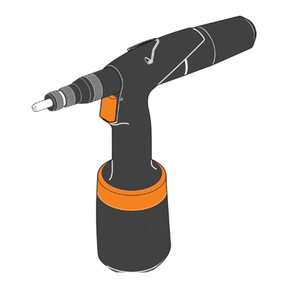
- Page 1 AirPower 4, 5 Models Z-14026001, Z-15026001 Repair Manual AirPower4 Model Z-14026001 AirPower 5 Model Z-15026001 Hydraulic Threaded Insert Tools...
-
Page 2: Table Of Contents
Repair manual (version 3 modified) specified for riveting tools serie 4 (AirPower 4, EZM4000, E-412NA, ON-4, AS4, RK-55-SPS) specified for riveting tools serie 5 (AirPower 5, RK-59-SPS) Content: Abbreviations General instructions Proper function of riveting tool Assembly drawing of riveting tool Informative list of parts of riveting tool Instructions for assembling and disassembling –... -
Page 3: Proper Function Of Riveting Tool
3. Proper function of riveting tool: Operator activity Tool function Connect the riveting tool to CA, if the tool is CA does not leak, motor does not rotate equiped with main valve, turn it on. Pos. 74 is on the front extreme position, not pressed Put a rivet on pos. -
Page 4: Assembly Drawing Of Riveting Tool
4. Assembly drawing of riveting tool – serie 4: - 3 -... - Page 5 4. Assembly drawing of riveting tool – serie 5: - 4 -...
- Page 6 5. Informative list of spare parts of riveting tool – serie 4: Position Article Nr. Name of part D-14001XX Mandrels S-14003XX Anvils complete D-1400400 Joint sleeve D-1400500 Counternut D-1401000 Joint shaft S-1400600 Front nozzle complete 0901 D-1400610 Front nozzle body 0902 D-1400620 Front nozzle with scale...
- Page 7 5. Informative list of spare parts of riveting tool – serie 5: Position Article Nr. Name of part D-14001XX (D-15001XX) Mandrels S-14003XX Anvils complete D-1500400 Joint sleeve D-1500500 Counternut D-1501000 Joint shaft S-1500600 Front nozzle complete 0901 D-1400610 Front nozzle body 0902 D-1500620 Front nozzle with scale...
-
Page 8: Instructions For Assembling And Disassembling - Steps
6. Instructions for assembling and disassembling – steps 1-19: Step 1 Disassembly: Put MP14 on pos. 80, loosen and screw out pos. 65 and pos. 80. Assembly: Screw on pos. 65 with pos. 80, put on MP14, tighten and put coloured warranty plug. In case of using new parts pos. - Page 9 Step 2 Disassembly: Release pos. A45. Assembly: Put on pos. A45. - 8 -...
- Page 10 Step 3 Disassembly: Put MP15B on pos. 59, then press MP15B with pliers, screw out pos. 61 with imbus key nr. 3 and take out pos. 60 and pos. 59. Then pour out the hydraulic oil from the riveting tool to the suitable container.
- Page 11 Step 4 Disassembly: Put MP11 to the locks pos. 79, divert pos. 66 from MP11 (because the surface of pos. 66 might be damaged) and screw out pos. 79. Assembly: Screw pos. 79 on thread pos. A36, put MP11 on locks pos. 79, divert pos. 66 from MP 11 (because the surface of pos.
- Page 12 Step 5 Disassembly: Screw out pos. 50 (2x) with imbus key nr. 5, put out pos. 55 with pos. 66, 68, 69 and pos. A47 with pos. 67. Put pos. 66 with pos. 68 out., take pos. 69 out with MP32, be careful and do not damage recess in pos.
- Page 13 Step 6 Disassembly: Put the blow gun on the outlet (see the detail) and release a small amount of CA, pos. A39, A40 and A41 blow out off the pos. A23, it is necessary to catch them (e.g. to the cloth). Assembly: Inser pos.
- Page 14 Step 7 Disassembly: Loosen pos. A36 with MP33 key, screw out and put out from pos. A23. Assembly. Check the sealing of pos. 40 (see Step 22). Put pos. A36 on pos. A23, screw on and tighten with MP33 key. ! Check the proper position of the sealing! - 13 -...
- Page 15 Step 8 Disassembly: Put MP14 on pos. 81 in marked area (ending), loosen and screw out pos. 81 with pos. 38, put out pos. 39 and take out pos. 31 from pos. 26. Assembly: Put pos. 31 on pin pos. 39, put pos. 39 to pos. 81, screw this complete on pos. 26 and tighten with MP14.
- Page 16 Step 9 Disassembly: Take out pos. 29 (4x) with the help of MP32. Screw out pos. A35 with pos. 25 from pos. A23 with hook spanner 30-32 (MP28). Take out pos. 25 and pos. 28 (serie 5 only) serie 4 serie 5 Assembly: Put pos.
- Page 17 Step 10 Disassembly: Put out pos. A25 Assembly: Put on pos. A25 and move around a slight amount so that hexagon pos. A25 and pos. 8 match, then move pos. A25 to the stop. Turn pos. 1 to check if the installation was successful, rotation in pos.
- Page 18 Step 11 Disassembly: Screw out pos. 3 and pos. 1 Assembly: Screw pos. 1 on pos. 6 to the stop and move back a slight amount, so that hexagon pos. 1 and pos. 6 match. Put pos. 3 on pos. 1 and pos. 6, so that hexagon socket pos. 3 match with hexagon pos. 1 and pos.
- Page 19 Step 12 Disassembly: Screw out pos. 9 with wrench 24 and put out pos. 10 with MP32. Assembly: Put pos. 10 on pos. 9, screw on pos. 9 and tighten with wrench 24. - 18 -...
- Page 20 Step 13 Disassembly: Put wrenches 12 (2x) on pos. 6 and pos. 7, loosen and screw out pos. 6, put hex key on pos. 8 and from the side of the dart screw out pos. 7. Assembly: Screw pos. 7 on pos. 8 (recess in direction to pos. A24) so that the lenght between pos. 7 and pos. A24 is 1 mm (see the detail).
- Page 21 Step 14 Disassembly: Put pos. 8 out of pos. A24 in the direction of the dart. Assembly: Put pos 8 on to pos. A24. - 20 -...
- Page 22 Step 15 Disassembly: Put pos. A24 out of pos. A23 in the direction of the dart. ! Be careful and do not damage the sealing in pos. A23! Assembly: Lubricate external surface of pos. A24, inner surface of pos. A23 and related sealing of pos. A24 and pos.
- Page 23 Step 16 Disassembly: Place a pin cca 2,8 mm in diametre to the pos. 76 and knock out with a hammer from pos. A23, put out pos. 74. Assembly: Put on pos. 74, put on pos. 76 and beat in with hammer and a pin cca 2,8 mm in diametre so that the pos.
- Page 24 Step 17 Disassembly: Put MP10 to the locks of pos. A46 and screw out together with pos. 73, take pos. 73 out of pos. A46. Assembly: Screw pos. A46 on pos. 23 with the help of MP10, so that the front sides of both positions were neck and neck, then insert pos.
- Page 25 Step 18 Disassembly: Take pos. 16 out of pos. A23. Assembly: Put pos. 16 on pos. A23. - 24 -...
-
Page 26: Instructions For Assembling And Disassembling Of Chosen Sub-Assemblies - Steps
6. Instructions for assembling and disassembling of chosen sub-assemblies – steps 20-25 Step 20 – pos. A45 Disassembly: Put pos. 64 out of pos. 62, take pos. 63 out of pos. 62 with MP32, be careful and do not damage recess in pos. - Page 27 Step 21 – pos. A36 Disassembly: Put pos. 42 and pos. 40 out of pos. 41 with the help of MP32, while putting out be careful and do not damage recess in pos. 41. serie 4 serie 5 Assembly: Put pos. 42 on pos. 41, be careful while putting it on and do not damage pos. 42 with a thread on pos.
- Page 28 Step 22 – pos. A25 Disassembly: Put pos. 27 and pos. 23 out of pos. 24 with the help of MP32, while putting out be careful and do not damage recesses in pos. 24. Assembly: Put pos. 27 on pos. 24. Put pos. 23 into the recess pos. 24. ! Is necessary to keep the orientation pos.
- Page 29 Step 23 – pos. A47 a pos. 67 Disassembly: Put pos. 52 and pos. 53 out of pos. 54 with MP32. Be careful and do not damage recesses in pos. 54. Put a imbus key nr. 5 into the hex. in pos. A43 and screw the complete out of pos. 54. Disassembly pos.
- Page 30 Step 24 – pos. 9 Disassembly: Grip the set (pos. 9) into a vice and mechanically take off (break up) pos. 0907. ! Attention, wearing protective eyewear during this operation is strongly recommended! Be careful not to damage other parts and also not to lose pos. 0910, which may be „blown out“ by interaction with pos.
- Page 31 Step 25 – pos. A35 Disassembly: Put wrench MP17 into hexagon socket pos. 32, put wrench MP18 into recess pos. 37, loosen and screw out pos. 35. Put out pos. 37, pos. 36 and pos. 26. Take pos. 34 out of pos. 33 with help MP 31.
-
Page 32: List Of Defects Of Riveting Tool
8. List of defects of riveting tool: tears threads in the rivet nuts does not wind up or winds up slowly keeps winding up keeps winding out does not wind out or winds out slowly (while riveting) does not wind out with button does not rivet oil leaks CA distribution... - Page 33 disassembly pos. A35 BEM is OK disassembly pos.38,39,31 check tightening of pos. A35 check pos. 29,39,A35 29,39,A35 BEM is OK disassembly and check pos.38,39,31 31,39 disassembly and check pos. A35,29 A35,29 disassembly pos. 28,26,36,35,37 9,25 check pos. 35,36,37 35,36,37 further see D10 disassembly pos.
- Page 34 disassembly pos. A35,29 disassembly pos. 28,26,36,35,37 9,25 check pos. 35 (fron),26 (inner surface) 35,26 disassembly pos. A25 disassembly pos. 27 disassembly pos. 3,1,9 11,12 check "cracking" pos. 1,6,8 if pos. 6 damaged, disassembly if pos. 8 damaged, disassembly 8,9,10,14,13 press and release pos. 74 NO outlet from pos.
-
Page 35: Service Set
10. Service set: Order Nr. of service set is S-1002002. - 34 -... - Page 36 Service stand for assembling and disassembling of riveting tool is not piece of service set. Order Nr. of service stand is S-1005000. 11. List of special tools in the service set: S-1002002 Service set for AP tool (version 2016) Marked Article Nr.
- Page 37 251 Cree Crescent, Winnipeg, MB Canada R3J 3X4 Tel: 204 837 8361 • 1 800 563 1293 info@applifast.com...
Need help?
Do you have a question about the AirPower4 and is the answer not in the manual?
Questions and answers