Advertisement
Quick Links
PARTS LIST
Part
Qty
A
1
ASI LOCKING HANDLE with KEYS
B
2
8-32 X .25 SLT TR HD MS
C
1
CAM WITH PINS
D
2
4180 LOCK RODS - PAINTED
E
1
CAM PLATE FOR ASI LOCKING HANDLE
F
1
SPRING RETAINER CLIP
G
4
1/4-20 X .50 WHIZ-LOCK SCREWS, 3/8" HEX DRIVE
H
4
1/4-20 KEPS NUTS, 7/16" HEX DRIVE
I
4
#14 x 1 TORX DRIVE WOOD SCREWS
TOOLS NEEDED
Flathead
7/16"
Screwdriver
Wrench
4 1 4 0 C A B I N E T
Description
3/8" Socket
Hand
Wrench
Drill
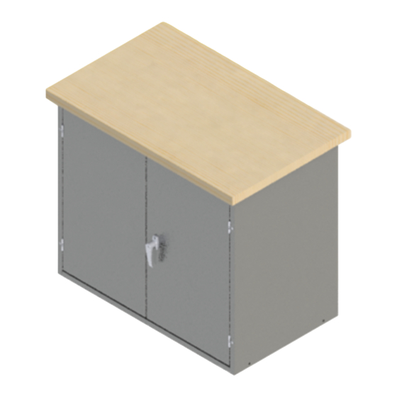
CABINET ASSEMBLY
5/32"
T-30
Drill Bit
Torx Bit
hellomontisa.com
4140
REV 1 4.12.2023
Image
Advertisement

Related Manuals for MONTISA 4140


Summary of Contents for MONTISA 4140
- Page 1 4140 CABINET ASSEMBLY REV 1 4.12.2023 PARTS LIST 4 1 4 0 C A B I N E T Part Description Image ASI LOCKING HANDLE with KEYS 8-32 X .25 SLT TR HD MS CAM WITH PINS 4180 LOCK RODS - PAINTED...
- Page 2 4140 ASSEMBLY INSTRUCTIONS Install the Locking-Handle Assembly, see Figure 1. Position and secure handle (Part A) to door panel by using the (2) 8-32 x .25" long Screws (Part B). Position the Cam with Pins (Part C) on the handle shaft.
Need help?
Do you have a question about the 4140 and is the answer not in the manual?
Questions and answers