Table of Contents
Advertisement
Quick Links
MA 4040 160W
4 Zone Mixer Amplifier
CH 1
CH 2
GAIN
GAIN
-10
+10
-10
+10
HF
HF
-10
+10
-10
+10
LF
LF
-10
+10
-10
+10
MUTE
MUTE
5
5
4
6
4
6
3
7
3
7
2
8
2
8
9
9
1
1
VOL
VOL
0
10
0
10
Z1
Z2
Z1
Z2
Z1
Z3
Z4
Z3
Z4
Z3
SERIAL NUMBER
110-120V~
POWER INPUT:
110-240V~50/60Hz
110-120V~60Hz - FUSE: T6.3A 250V
220-240V~50/60Hz - FUSE: T3.15A 250V
User Manual
CH 3
CH 4
GAIN
GAIN
-10
+10
-10
+10
HF
HF
-10
+10
-10
+10
LF
LF
-10
+10
-10
+10
MUTE
MUTE
5
5
4
6
4
6
3
7
3
7
3
2
8
2
8
2
9
9
1
1
1
VOL
VOL
0
10
0
10
Z2
Z1
Z2
Z1
Z4
Z3
Z4
Z3
MONITOR
MONITOR
PRIORITY
LINE OUTPUT
1W
8
HOT
G
+
–
+
220-240V~
CAUTION
RISK OF ELECTRIC SHOCK
DO NOT OPEN. NO USER
SERVICABLE PARTS INSIDE
WARNING:
TO REDUCE THE RISK OF FIRE OR ELECTRIC SHOCK.
DO NOT EXPOSE THIS EQUIPMENT TO RAIN OR MOISTURE
www.cleveracoustics.co.uk
POWER CONSUMPTION (max.): 180W
Order code: CRAM32
CH 5
MA 4040 Mixer Ampli er
GAIN
-10
+10
HF
-10
+10
LF
-10
+10
MUTE
5
4
6
7
8
9
0
10
0
10
VOL
PHONE
MONITOR
0
10
VOLUME
VOLUME
Z2
Z4
PHONE
TEL PAGING
COM
GND
LINE
PHANTOM
TEL
ZONE
VOLUME
PHANTOM
PHANTOM
LINE
MIC
LINE
CH5
CH4
LINE
LINE
L
R
CH3
ZONE 1
ZONE 2
VOLUME
VOLUME
5
5
4
6
4
6
3
7
3
7
2
8
2
8
1
9
1
9
0
10
0
10
MONITOR
MONITOR
ZONE 3
ZONE 4
VOLUME
VOLUME
5
5
4
6
4
6
3
7
3
7
2
8
2
8
1
9
1
9
0
10
0
10
MONITOR
MONITOR
POWER AMP OUTPUT
LINE OUT - BAL/UNBAL
ZONE 1
G
–
+
COM
4
8
MIC
POWER AMP OUTPUT
LINE OUT - BAL/UNBAL
ZONE 2
G
–
+
COM
4
8
CH1
POWER AMP OUTPUT
LINE OUT - BAL/UNBAL
ZONE 3
G
–
+
COM
4
8
MIC
POWER AMP OUTPUT
LINE OUT - BAL/UNBAL
ZONE 4
G
–
+
COM
4
8
CH2
POWER
ON
OFF
25V
70V
100V
25V
70V
100V
25V
70V
100V
25V
70V
100V
Advertisement
Table of Contents

Related Manuals for Clever Acoustics MA 4040


Summary of Contents for Clever Acoustics MA 4040
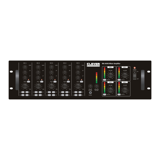
- Page 1 MA 4040 160W 4 Zone Mixer Amplifier User Manual CH 1 CH 2 CH 3 CH 4 CH 5 MA 4040 Mixer Ampli er GAIN GAIN GAIN GAIN GAIN ZONE 1 ZONE 2 POWER VOLUME VOLUME MONITOR MONITOR MUTE MUTE...
-
Page 2: Safety Advice
• Do not expose to flammable sources, liquids or gases. • If your product fails to function correctly, stop use • Always disconnect the power from the mains when immediately. Pack the unit securely (preferably in the equipment is not in use or before cleaning! Only handle original packing material), and return it to your Prolight the power-cable by the plug. Never pull out the plug by dealer for service. pulling the power-cable. • Only use fuses of same type and rating. • Make sure that the available voltage • Repairs, servicing and power connection must only be is between 240V, 50Hz AC. carried out by a qualified technician. THIS UNIT CONTAINS • Make sure that the power cable is never crimped or NO USER SERVICEABLE PARTS. damaged. Check the equipment and the power cable • WARRANTY: Three years from date of purchase. periodically. OPERATING DETERMINATIONS If this equipment is operated in any other way, than those described in this manual, the product may suffer damage and the warranty becomes void. Incorrect operation may lead to danger e.g: short-circuit, burns and electric shocks etc. Do not endanger your own safety and the safety of others! Incorrect installation or use can cause serious damage to people and/or property. www.cleveracoustics.co.uk MA 4040 160W Mixer Amplifier User Manual... - Page 3 Product overview & technical specifications MA 4040 160W 4 Zone Mixer Amplifier The MA 4040 4 Zone Mixer Amplifier is ideal for systems where multiple zones are required. Designed for use in venues such as schools, churches, entertainment venues or commercial buildings, the MA 4040 offers multi zone audio routing coupled with four independent 40Wrms amplifiers. The MA 4040 4 zone mixer amplifier has five input channels, each with selectable independent output routing, input gain, treble bass and volume controls. Input channels 1 thru 3 are via XLR/Jack combo sockets, each with Line/Mic/Mic+Phantom selection, input channels 4 & 5 are via stereo line RCA phono level inputs. Four output zones each feature LED VU indicators, monitor selection and volume controls with outputs for line level, low impedance (4-8Ω) and constant voltage speaker systems (25V, 75V & 100V). The on-board monitor facility, selectable for each zone output features both a line level audio and 1W 8Ω loudspeaker output suitable for driving a loudspeaker local to the MA 4040 zone mixer. • Four output zones each with level control and monitor selection Specifications MA 4040 160W Mixer Amplifier • Four independent 40Wrms amplifiers outputting to 4-8Ω or 25, 70, 100V Power output 4 x 40Wrms (4 x 90W peak) • Five input channels: Speaker outputs 25V, 70V, 100V and 4-8Ω Channels 1-3 are via XLR/Jack combo sockets, Sensitivity - CH1–3: -42dB/-38dB each with Line/Mic/Mic+Phantom selection (48V) (Mic bal./unbal./), -26dB/-20dB Channels 4 and 5 are via phono (RCA) stereo line level inputs (Line bal./unbal.)
- Page 4 01 - Gain control 12 - Zone output level control 22 - Priority control terminals 02 - HF level control 13 - Monitor output selector 23 - Telephone/paging input (TEL) 03 - LF level control 14 - Power LED 24 - Telephone/paging input zone selection & volume control 04 - Mute switch 15 - Power switch 25 - Stereo LINE inputs 05 - Mute LED 16 - Cooling fan 26 - Mono MIC/LINE inputs 06 - Input channel level control 17 - AC mains power input 27 - Input sensitivity and phantom 07 - Zone selection switches 18 - AC mains fuse power control 08 - Headphone level control 19 - AC voltage selector 28 - Balanced line level zone outputs 09 - Headphone output 20 - Monitor (MIX) line output 29 - Power amplifier outputs 10 - LED VU output meter 21 - Monitor loudspeaker output (1W 8Ω) 11 - Monitor level control www.cleveracoustics.co.uk MA 4040 160W Mixer Amplifier User Manual...
- Page 5 5. Mute LED: The mute LED provides a visual indication when the input channel is in mute status. 6. Input channel level control: The gain control is used to adjust the input gain (level) for each of the zone mixers input channels. Turn the level control anti clockwise to the lowest setting, or turn clockwise to adjust to the highest setting. Adjustments should be made gradually to avoid any sudden changes to the audio output. If the audio source appears to sound distorted, a reduction in gain may be required. The input channel level control adjusts the level of the selected input channel within the main mix. 7. Zone selection switches: Each of the five input channels may be routed to any of the four output zones. Press the switch to the IN position to route the selected input channel to the chosen output zone. 8. Headphone level control: The headphone output volume is adjustable. Turn the level control anti clockwise to the lowest setting, or turn clockwise to adjust to the highest setting. 9. Headphone output: Utilising a standard 3.5mm stereo jack socket, the headphone output is used alongside the monitor function to check the output of individual output zones. If none of the output zones are selected using the monitor selection switches, the headphone output will be muted. www.cleveracoustics.co.uk MA 4040 160W Mixer Amplifier User Manual...
-
Page 6: Power Switch
14. Power LED: The Power LED will illuminate to indicate the zone mixer is powered on. If the power LED is not illuminated, check first the position of the on/off switch and then check the mains (including fuse) or DC power supply. 15. Power switch: On/Off control for the zone amplifier. Note: The on/off power switch does not have any control over the 24V DC power input. 16. Cooling fan: The MA 4040 is fan cooled. The cooling fan will start when the internal temperature sensor reaches 50°C. The fan speed will vary according to the internal temperature of the amplifier. Do not block or obstruct the fan port on the rear panel or the air vents on the top or side panels. 17. AC mains power input: Before connecting the amplifier to the local mains voltage outlet should be checked to ensure the available supply is 240V~AC 50Hz. This product is CLASS1 and requires a protective mains earth to be connected at all times. DO NOT remove or disconnect the earth. 18. AC mains fuse: Disconnect from the mains power supply before attempting to replace the mains fuse. Replacement mains fuses must be the same rating as the original. T3.15AL 250V for 220-240V AC mains supply or T6.3AL 250V for 110-120V AC mains supply. www.cleveracoustics.co.uk MA 4040 160W Mixer Amplifier User Manual... - Page 7 For emergency paging, the MA 4040 is equipped with a balanced audio TEL input, activated automatically upon the MA 4040 detecting an audio signal present on the TEL input terminals. The input carries the highest priority and will override all other inputs & priority functions on the amplifier. 24. Telephone/paging input zone selection & volume control: The TEL input features zone control and input volume control. To route the TEL signal to a desired output zone, move the corresponding DIP switch to the down (ON) position. The input volume for the TEL signal may be controlled by the recessed volume control potentiometer. For most applications, it may be best practice to set the minimum possible level to prevent unwanted activation of the priority input. Turn the potentiometer clockwise to increase the volume. 25. Stereo LINE inputs: A stereo audio input is provided for sources such as FM Tuners, CD Players or MP3 Players. The input features a pair of unbalanced phono (RCA) inputs suitable for line level audio input. 26. Mono MIC/LINE inputs: Channels 1, 2 & 3 all feature mono audio inputs, each with selector for use with MIC/MIC+Phantom/ Line signals. The audio input is designed to accept a balanced audio signal via XLR or 6.35mm (¼”) TRS jack. Channel 1 features automatic priority override over channels 2, 3 and 4. If this feature is not required, the user must refer to a service technician who will be able to follow the instructions on page 9 to defeat the voice priority function. www.cleveracoustics.co.uk MA 4040 160W Mixer Amplifier User Manual...
-
Page 8: Power On/Off Procedure
28. Balanced line level zone outputs: The MA 4040 features four, independent zone outputs each utilising barrier strip terminals for the balanced audio output (1.7V). The line level outputs may be used to feed signal to external amplification where additional amplification is required. If the amplifier connected only requires an unbalanced signal, the output contacts “+” and “G” should be used. 29. Power amplifier outputs: Each of the four output zones on the MA 4040 features both low impedance and constant voltage loudspeaker outputs. Each output zone may be used to output into either low impedance (4-8Ω) or constant voltage (25V, 70V, 100V). Do not use more than one pair of output terminals on any one output zone. Care should be taken when connecting to the outputs to ensure the load impedance is above the minimum load specified for the output. Power on/off procedure: Prior to making any connection to the mains power or audio inputs/outputs, turn all level controls counter clockwise to the “0” position and all tone (equaliser) controls to the mid (zero) point. Deselect all monitor and zone selection controls. Switch on the zone mixer and any audio sources (MP3 players, CD players, Microphones etc) before powering the systems amplifier ON. The last product to be switched on should be the power/slave amplifiers to prevent any unwanted noise or potential damage to speakers or amplifiers. If you wish to power off the system, turn the amplifier’s master volume control counter clockwise to the “0” position before switching the amplifier OFF before any audio sources are switched off. By following this procedure it will prevent acoustic shocks to the speakers or potential damage to system components. After connecting all audio sources and powering on the system, adjust the level of each audio input, select the zone routing in order to achieve the desired “mix” for each zone. Care should be taken to when adjusting microphone input volumes and the master volume, adjust both of these in small increment’s to avoid feedback (howl around). The goal is to achieve a clear balance between music and voice ensuring announcements can be clearly heard. www.cleveracoustics.co.uk MA 4040 160W Mixer Amplifier User Manual... - Page 9 Operating instructions MIC priority: During normal operation the MA 4040 features priority for MIC1 over the other microphone and line inputs. For certain applications, the installation engineer may need to defeat the MIC1 priority function. In order to do this, the product must be fully disconnected from any AC or DC power sources, and disconnected from all inputs/outputs. Remove the 15 screws from the outer casing as per the diagram below and keep in a safe location. Remove the upper casing and place to one side. Locate the PCB towards the rear of the unit as pictured below. Carefully move the jumper from the "ON" position to the "OFF" position. Refit the outer casing, taking care to avoid damaging the unit. Refit all of the screws to fully secure the outer casing. Top of Mixer Side 1 of Side 2 of Mixer Mixer Rear of Mixer www.cleveracoustics.co.uk MA 4040 160W Mixer Amplifier User Manual...
- Page 10 Typical panel connections Contact “Voice Priority” Microphone Column speaker Desktop Mic Speaker Amplifier Horn Monitor speaker Speaker C ontact "V OIC E P R IO R Recorder Mains PA Amplifier CD Player AM/FM Tuner Recorder www.cleveracoustics.co.uk MA 4040 160W Mixer Amplifier User Manual...
-
Page 11: Rack Installation
Installation Rack installation: The MA series is rack mountable. The rack you use should be a double door rack where you can open the front and rear panel. When mounting the amplifier into the rack, please make sure that there is enough space around the amplifier. Be careful when mounting the amplifier into the rack. Put the heaviest products into the lower part of the rack. The front panel is not designed to absorb acceleration forces occurring during transportation. Inputs: Short cables runs improve the sound quality remarkably. Input cables should be short and direct, since high frequencies will mostly be absorbed if the cables are unnecessarily long. Besides that a longer cable may lead to humming and noise problems. If the cable runs are unavoidable, you should use balanced cables. Outputs: The high damping factor of your amplifier supplies a clear sound reproduction. Unnecessarily long and thin cables used for low impedance (4-16Ω) speakers will influence the damping factor and thus the low frequencies in a negative way. In order to safeguard good sound quality, the damping factor should lie around 50. The longer a cable has to be the thicker it should be. For longer cable runs please ensure the 100V outputs are used for 100V speakers. Connect your speaker systems via the speaker terminals (COM = -VE) Examples: 1) COM + 4-16Ω 2) COM + 70V 3) COM + 100V Note: Please do not use more than one pair of output terminals on any one output zone. www.cleveracoustics.co.uk MA 4040 160W Mixer Amplifier User Manual... -
Page 12: Weee Notice
Correct Disposal of this Product (Waste Electrical & Electronic Equipment) (Applicable in the European Union and other European countries with separate collection systems) This marking shown on the product or its literature, indicates that it should not be disposed with other household wastes at the end of its working life. To prevent possible harm to the environment or human health from uncontrolled waste disposal, please separate this from other types of wastes and recycle it responsibly to promote the sustainable reuse of material resources. Household users should contact either the retailer where they purchased this product, or their local government office, for details of where and how they can take this item for environmentally safe recycling. Business users should contact their supplier and check the terms and conditions of the purchase contract. This product should not be mixed with other commercial wastes for disposal. www.cleveracoustics.co.uk MA 4040 160W Mixer Amplifier User Manual...
Need help?
Do you have a question about the MA 4040 and is the answer not in the manual?
Questions and answers