Table of Contents
Advertisement
Quick Links
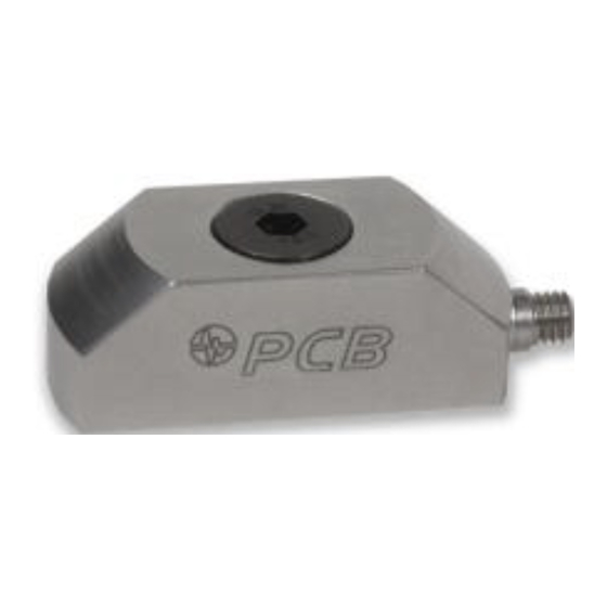
Model RHM240A01
Industrial dynamic strain sensor, ICP® quartz, 100 mV/microstrain, +/-50 microstrain range, M6
x 1 thd, RoHS compliant
Installation and Operating Manual
For assistance with the operation of this product,
contact the PCB Piezotronics, Inc.
Toll-free: 716-684-0001
24-hour SensorLine: 716-684-0001
Fax: 716-684-0987
E-mail: info@pcb.com
Web: www.pcb.com
Advertisement
Table of Contents

Subscribe to Our Youtube Channel
Related Manuals for PCB Piezotronics ICP RHM240A01


Summary of Contents for PCB Piezotronics ICP RHM240A01
- Page 1 Industrial dynamic strain sensor, ICP® quartz, 100 mV/microstrain, +/-50 microstrain range, M6 x 1 thd, RoHS compliant Installation and Operating Manual For assistance with the operation of this product, contact the PCB Piezotronics, Inc. Toll-free: 716-684-0001 24-hour SensorLine: 716-684-0001 Fax: 716-684-0987 E-mail: info@pcb.com...
-
Page 2: Repair And Maintenance
Assistance is needed to safely operate equipment PCB Piezotronics is an ISO-9001 certified company whose Damage is visible or suspected calibration services are accredited by A2LA to ISO/IEC Equipment fails or malfunctions 17025, with full traceability to SI through N.I.S.T. - Page 3 CAUTION Refers to hazards that could damage the instrument. NOTE Indicates tips, recommendations and important information. The notes simplify processes and contain additional information on particular operating steps. The following symbols may be found on the equipment described in this manual: This symbol on the unit indicates that high voltage may be present.
- Page 4 PCB工业监视和测量设备 - 中国RoHS2公布表 PCB Industrial Monitoring and Measuring Equipment - China RoHS 2 Disclosure Table 有害物质 镉 汞 铅 (Pb) 六价铬 (Cr(VI)) 多溴联苯 (PBB) 多溴二苯醚 (PBDE) 部件名称 (Hg) (Cd) 住房 PCB板 电气连接器 压电晶体 环氧 铁氟龙 电子 厚膜基板 电线 电缆 塑料 焊接...
- Page 5 Component Name Hazardous Substances Lead (Pb) Mercury (Hg) Cadmium (Cd) Chromium VI Polybrominated Polybrominated Compounds Biphenyls (PBB) Diphenyl Ethers (Cr(VI)) (PBDE) Housing PCB Board Electrical Connectors Piezoelectric Crystals Epoxy Teflon Electronics Thick Film Substrate Wires Cables Plastic Solder Copper Alloy/Brass This table is prepared in accordance with the provisions of SJ/T 11364.
- Page 6 QUARTZ STRAIN SENSOR OPERATION MANUAL 1.0 INTRODUCTION ICP quartz strain sensors are well suited for continuous, unattended strain monitoring in harsh factory environments. ICP quartz strain sensors incorporate a built-in MOSFET Also, ICP sensor cost-per-channel is substantially lower, since microelectronic amplifier.
-
Page 7: Installation
QUARTZ STRAIN SENSOR OPERATION MANUAL output readings. The supplied screw allows proper strain transmission 3.0 INSTALLATION to the sensor while holding the sensor in place. Properly machined holes for the mounting screw will ensure proper vertical orientation of the sensor. Refer to the installation drawing for additional mounting details. - Page 8 QUARTZ STRAIN SENSOR OPERATION MANUAL 4.0 OPERATION 4.1 TYPICAL ICP SYSTEM CONFIGURATION Sensors with built-in ICP circuitry require a constant-current excitation voltage for operation. The enclosed Specification Sheet provides specific power requirements. Required supply voltage is normally 20 to 30 VDC, while the constant current required ranges from 2 to 20 mA.
- Page 9 QUARTZ STRAIN SENSOR OPERATION MANUAL 5.0 POLARITY The discharge time constant represents the decay rate of an input signal. One DTC represents the amount of time taken for Extension of the mounting area of an ICP strain sensor the signal to decay to 37% of the initial peak value. As produces a positive-going voltage output.
-
Page 10: Troubleshooting
QUARTZ STRAIN SENSOR OPERATION MANUAL 9.0 TROUBLESHOOTING Observe the following precautions when using the sensor: When a PCB signal conditioner with any of the following indicators are used, turn the power on and observe the A. Do not exceed the maximum strain levels for the strain voltmeter (or LED's) on the front panel. - Page 11 All specifications are at room temperature unless otherwise specified. 3425 Walden Avenue, Depew, NY 14043 In the interest of constant product improvement, we reserve the right to change specifications without notice. ® is a registered trademark of PCB Piezotronics, Inc.
- Page 12 PCB Piezotronics Inc. claims proprietary rights in REVISIONS the information disclosed hereon. Neither it nor any reproduction thereof will be disclosed to others DESCRIPTION without the written consent of PCB Piezotronics Inc. ADDED NOTE #4 54044 .67 [17.0] ELECTRICAL CONNECTOR...
Need help?
Do you have a question about the ICP RHM240A01 and is the answer not in the manual?
Questions and answers