Table of Contents
Advertisement
Quick Links
OWNER'S
MANUAL
MODEL NO.
917.257360
Caution:
Read and follow
all Safety
Rules
and Instructions
Before
Operating
This Equipment
®
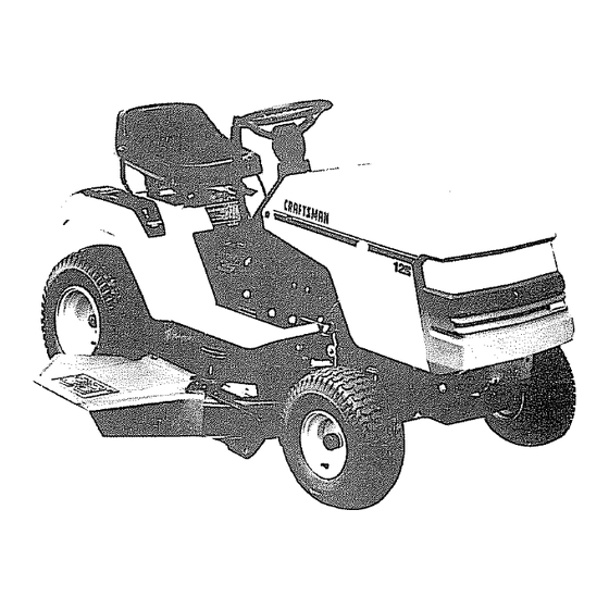
12.0 HP HC
ELECTRIC START
38" MOWER
AUTOMATIC
(HYDROSTATIC)
LAWN
TRACTOR
° Assembly
° Operation
o Maintenance
o Service and Adjustment
o Repair Parts
Sears, Roebuck
and Co., Chicago,
IL 60684 U.S.A.
Advertisement
Table of Contents

Related Manuals for Craftsman 917.25736


Summary of Contents for Craftsman 917.25736
- Page 1 OWNER'S MANUAL MODEL NO. 917.257360 Caution: Read and follow all Safety Rules and Instructions Before Operating This Equipment Sears, Roebuck 12.0 HP HC ELECTRIC START 38" MOWER AUTOMATIC (HYDROSTATIC) LAWN TRACTOR ° Assembly ° Operation o Maintenance o Service and Adjustment o Repair Parts and Co., Chicago, IL 60684 U.S.A.
-
Page 2: Safety Rules
PLUG TO PREVENT ACCIDENTAL STARTING WHEN SETTING-UP, TRANSPORTING, ADJUSTING OR MAKING CAUTION: ALWAYS DISCONNECT SPARK PLUG WIREAND PLACE WIRE WHERE IT CANNOTCONTACT SPARK REPAtRS, SAFETY STAN DARDS REQUIRE O PERATOR PRESENCE CONTRO LS TO MINIMIZE THE RISK OF INJ URY. YOUR UNIT IS EQUIPPED WITH SUCH CONTROLS, DO NOT ATTEMPT TO DEFEAT THE FUNCTION OF THE OPERATOR TRAINING:... -
Page 3: Specifications
CONGRATULATIONS on your purchase Tractor, it has been designed, engineered and manu- factured to give you the best possible dependability performance, Should you experience any problem you cannot easily remedy, please contact your nearest Department. We have competent, cians and the proper tools to service or repair this unit, Please read and retain this manual enable you to assemble and maintain your unit properly, Always observe the "SAFETY RULES",... - Page 4 SAFETY RULES ... PRODUCT SPECIFICATIONS CUSTOMER RESPONSIBILITIES WARRANTY ... TABLE OF CONTENTS ... INDEX ... TRACTOR ACCESSORIES ASSEMBLY INDEX Accessories ... Adjustments: Brake ... Carburetor..Mower Blade Drive Belt ...20 Mower Front-To-Back ... 19 Side-To-Side ... 19 Throttle Control Cable ... 25 Air Filter, Engine ...
-
Page 5: Accessories
ACCEGGORmES AND ATTACHMENTS These accessories and attachments were available when the unit was purchased. catalog and service centers Most Sears stores can order these items for you when you provide the model number of your tractor. ENGINE SPARK PLUG MUFFLER AIR FILTER PERFORMANCE Sears offers a wide variety of attachments... - Page 6 CONTENTS Parts Bag contents shown full size "_ © (1) Locknut 1/2 - 20 (1) 2-3/8" Dia, Washer (1) Shoulder Bolt 5/16-18 (1) Hex Bolt 1/2-13 x 1 (1) Lockwasher (1) Washer 17/32 x 1-3/16 x 12 Ga, (2) Hex Bolts 1/4 - 20 x 3/4 (2) Hex Nuts 1/4- 20 (2) Washers 9/32 x 5/8 x 16 Ga.
-
Page 7: Tools Required
TOOLS REQUIRED FOR ASSEMBLY A socket wrench set will make assembly easier wrench sizes are listed, (1) 5/15" wrench (1) 3/4" wrench (2) 7/16" wrenches Tire pressure gauge Screwdriver (1) 1/2" wrench (t) 9/16" wrench Utility knife When right and left hand is mentioned in this manual, it means when you are in the operating position (seated be- hind the steering wheel). - Page 8 ,,,,u HOW TO SET UP YOUR TRACTOR PREPARE BATTERY (See Fig. 2) CAUTION: Wear eye and face shield. Wash hands or clothing immediately if accidentally In contactwith battery acid. Do not smoke. Fumes from charged battery acid are explosive. Read the instructions Included with the batteryvent caps.
-
Page 9: Install Battery
INSTALL BATTERY (See Figs. 4 & 5) CAUTION: Do not short battery termi- nals. Before installing metal bracelets, wristwatch rings, etc. Positive terminal must be connected first to prevent sparking from acciden- tal grounding. Lift seat to raised position. Lower battery into fender well with battery terminals toward front of unit, Make sure battery rests in battery tray, Be sure battery drain tube has not come loose and is... -
Page 10: Know Your Tractor
, ,ill i, i,,,i i ,i KNOW YOUR TRACTOR READ THIS OWNER'S MANUALAND Compare the illustrations with your tractor to familiarize yourself with the locations of various controls and adjustments, Save this manual for future reference. THROTtLE/CHOKE CONTROL CLUTCH_RAKE CONTROL PARKING BRAKE LEVER Soars tractors conform to the safety standards of the American National Standards Institute. - Page 11 The operation of any tractor can result in foreign objects thrown into the eyes, which can result in severe eye damage or performing any adjustments or repairs. We recommend Wide Vision Safety Mask for over the spectacles or standard safety glasses, available at Sears Retail or Catalog Stores HOW TO USE YOUR TRACTOR TO SET PARKING BRAKE...
-
Page 12: Carburetor
TO OPERATE MOWER (See Fig. 8) Your unit is equipped with an operator presence sensing switch Any attempt by the operator to leave the seat with the engine running and the attachment clutch engaged will shut off the engine Select desired height of cut Engage mower by slowly moving attachment lever to "ENGAGED"... -
Page 13: Mowing Tips
(See Fig. 7) TO START ENGINE When starting engine for the first time or if engine has run out of fuel, it will take extra cranking time to move fuel from the tank to the engine. Depress the clutch/brake pedal and set the parking brake Place motion control lever in "NEUTRAL"... -
Page 14: General Recommendations
MAINTENANCE SCHEDULE REGULAR SERVICE Check Brake Operation Check Tire Pressure Check for Loose Fasteners Sharpen/Replace Mower Blades Lubricate Pivot Points Check Battery Level/Recharge Battery Clean and Terminals Check Pump Assembly Fluid Level Check Transmission Cooling Check Engine Oil Level Change Engine Oil Clean Air Filter Clean Air Screen inspect M uffler/Spar k Ai.'.i e ster... -
Page 15: Blade Care
TRACTOR Always observe safety rules when performing any mainte- nance TIRES Maintain proper aJr pressure in all tires (See "PROD- UCT SPECIFICATIONS" on page 3 of this manual) Keep tires free of gasoline, oil, or insect control chemi- cals which can harm rubber, Avoid stumps, stones, deep ruts, sharp objects and other hazards that may cause tire damage. - Page 16 i ,,,, ,,,,,, TRANSAXLE PUMP FLUID LEVEL 13 & 14) Check fluid level after every 25 hours of use Rear drawbar must be removed to check fluid revel Remove the four (4) fasteners to remove the drewbar Clean reservoir thoroughly before removing cap Check for proper fluid level in reservoir (should be above the "OIL LEVEL COLD"...
-
Page 17: Air Filter
AIR FILTER (See Fig. 16) Your engine will not run properly and may be damaged by using a dirty air filter. Replace paper cartridge once a year or after every 100 hours of operation, more often if tractor is used in very dusty, dirty conditions. Remove knob and cover, Remove cartridge nut and replace cartridge. -
Page 18: Mower Blade Drive Belt
SPARK PLUGS (See Fig. 17) Replace spark plugs at the beginning of each mowing season or after every 100 hours of use, whichever comes first. Spark plug type and gap setting is shown in "PROD- UCT SPECIFICATIONS" on page 3 of this manual. (See Fig. -
Page 19: Side-To-Side
;ERVICE AND ADJUSTMENTS (See Fig. 19) TO INSTALL MOWER Raise attachment lift lever to its highest position. Slide mower under tractor with discharge guard to right side of tractor. Install parallel link to front axle and mower with hinge pins Secure hinge pins with retainer springs, Install clutch rod in clutch lever and secure with retainer spring. -
Page 20: Service And Adjustments
SERVICE AND ADJUSTMENTS ADJUST MOWER BLADE (See Fig. 24) Your tractor has been manufactured readjust the mower blade drive belt to provide you with longer belt life. With the engine off and the lift lever in the highest position, move clutch lever up slowly until resistance is felt. distance from bottom of slot in dash to lift lever is greater than 4-1/2 inches, adjustment is necessary. - Page 21 SERVaCE AND ADJUSTMENTS TO ADJUST BRAKE (See Fig. 26) Your unit is equipped with an adjustable which is mounted on the right side of the transaxle If unit requires more than six (6) feet stopping distance at high speed in highest gear, then brake must be adjusted. Depress clutch/brake pedal and engage parking brake, Measure distance between brake operating arm and nut "A"...
- Page 22 SERVICE AND ADJUSTMENTS TO ADJUST MOTION CONTROL Fig. 29) "NEUTRAL" position of the motion control lever has been preset at the factory and adjustment should not be neces- sary If your unit tends to "creep" when the motion control lever is in "NEUTRAL"...
-
Page 23: To Start Engine
;ERV CE AN TO START ENGINE WITH A WEAK BATTERY (See Figs. 31 & 32) & CAUTION: Lead-acid ate explosive gases. Keep sparks, flame and smoking materials teries, Always wear eye protection when around batteries, If your battery is too weak to start the engine, it should be recharged If "jumper cables"... - Page 24 SERVNCE AND ADJUSTMENTS TO REMOVE HOOD AND GRILL ASSEMBLY (See Figs. 34 and Raise hood HOOD PIVOT ROD Unsnap headlight wire connector HINGE BRACKET Carefulty remove springs from hinge brackets Stand at side of tractor, Grasp hood, tilt forward and lift off hinge brackets, To reinstall, slide hood pivot rod into slot in hinge brackets, and carefully reinstall hood spring&...
-
Page 25: Throttle Control Cable
SERVICE AND ADJUSTMENTS ENGINE TO ADJUST THROTTLE CONTROL (See Fig. 36) The throttle control has been preset at the factory and ad- ustment should not be necessary Check ad ustment as described below before oosen ng cab e necessary, proceed as follows: With engine not running, move throttle control lever from "SLOW"... -
Page 26: Cleaning
Immediately prepare your tractor for storage at the end of the season or if the unit will not be used for 30 days or more CAUTION: Never store the tractor with gasoline in the tank inside a building where fumes may reach an open flame or spark. -
Page 27: Troubleshootbng
TROUBLESHOOTBNG ,,,,, PROBLEM CAUSE Will not start Out of fuel Engine not "CHOKED" Engine flooded Bad spark plug Dirty air filter Dirty fuel filter Waterin fuel Loose or damaged wiring Carburetor Engine vatves out of adjustment Herd to start Dirty air filter Bad sparkplug Weak or dead battery Dirty fuel filter... -
Page 28: Troubleshooting
TROUBLESHOOTING CAUSE PROBLEM i ,11 Engine continues to run Faulty operator-safety presence controI system when operator leaves seat with attachment clutch engaged Poor cut - uneven Worn, bent or loose blade Mower deck not level Build.up of grass, leaves, and trash under mower, Bent blade mandrel Mower blades will not Obstruction... -
Page 29: Repair Parts
REPAIR PARTS 12 HP 38" RIDING LAWN TRACTOR SCHEMATIC WHITE B_CK IGNITION SWITCH YOUR TRACTOR WITH A SPECIAL ALTERNATOR SYSTEM. CONNECTED BUT HAVE THEIR OWN ELECTRICAL BECAUSE OF THIS, THE BRIGHT- IGNITION SWITCH NESS OF THE LIGHTS WILL CHANGE WITH ENGINE SPEED. POSITION CIRCUIT AT IDLE THE LIGHTS WILL DIM,... - Page 30 REPAUR PARTS 12 HP 38" RIDING LAWN TRACTOR ELECTRICAL - - MODEL NUMBER i ... 917,257360...
- Page 31 REPABR PARTS 12 HP 38" RIDING LAWN TRACTOR ELECTRICAL KEY PART NO. NO. * STANDARD HARDWARE - - PURCHASE LOCALLY NO'[E: - - MODEL NUMBER DESCRIPTION 109310X Key, Molded 127441X Harness, Socket, Light 7662J Bulb, Light 4406 Switch, Ignition 123620X Cover, Switch, Key 124211X Nut, Ignition...
- Page 32 ,,oi, _> I,-- =.-==...
- Page 33 _o ... €O _m_mo_m_m_mmo_m_mbmml €O _o _ ×xx_×x_o_×_xx×× o_XXXXXXXXX ××yxy I I I J J j J J J J J...
- Page 34 REPAIR PARTS 12 HP 38" RiDiNG LAWN TRACTOR DRIVE 21 6 - - MODEL NUMBER 917.257360 OPTIONAL EQUIPMENT Spark Arrester 1<it...
- Page 35 REPAIR PARTS 12 HP 38" RIDING LAWN TRACTOR DRIVE KEY PART NO. NO. DESCRIPTION 127222X Pipe, Oil Drain 124136X Engine, Briggs and Stratton, 12 HP, Model Number 281707, Type Number 0412-01 Gasket 2949R 123528X Screw, Cap, Hex Head 121749X Washer 25/32 x 1-1/4 x 16 Gauge 122983X Muffler...
- Page 36 REPAIR PARTS 12 HP 38" RIDING LAWN TRACTOR STEERING AND FRONT AXLE -- MODEL NUMBER 917.257360 1"...
- Page 37 REPABR PARTS 12 HP 38" RIDING LAWN STEERING FRONT AXLE KEY PART HO. NO. DESCRIPTION 126604X010 Dash 74180512 Screw, Truss Head 5/16-18 x3/4 STD541431 *Nut, Keps 5/16-18 109816X Nyliner, Snap In 124434X Control, Throttle/Choke 19212010 Washer 126684X Washer 5/8 x 1/4 x 16 Gauge 124417X Boot, Shaft, Steering 126595X010...
-
Page 38: Lift Adjustment
REPAIR PARTS 12 HP 38" RIDING LAWN TRACTOR LIFT ADJUSTMENT f,.,, 16 ,_15 13 / /.11 - - MODEL NUMBER 917.257360... - Page 39 REPAIR PARTS 12 HP 38" RIDING LAWN TRACTOR LIFT ADJUSTMENT KEY PART NO, NO. DESCRIPTION 124429X Handle, Clutch, Mower 106932X Knob 106451X Bolt, Shoulder 106452X Bracket, Switch, Interlock 19171516 Washer 17/32 x15/16 x16 Gauge STD601005 *Screw, Hex, Tapping 106447X Support, Lever, Clutch 123549X Cap, Fuel 109202X...
- Page 40 REPAnR PARTS 12 HP 38" RIDING LAWN TRACTOR 38" MOWER 1_54 - - MODEL NUMBER 41 _ 41 '_ 9!7.257360...
-
Page 41: Installation
: EPARRPARTS 12 HP 38" RIDING LAWN TRACTOR 8" MOWER EY PART O. NO. DESCRIPTION 106085X V.Belt 121259X Housing 8417J Runner, R.H STD541437 *Nut, Crownlock 3/8-16 19111216 Washer 11/32 x 3/4 x16 Gauge STD533106 *Bolt, Carriage 5/16-18x5/8 105896X Bracket, Deflector 110452X Nut, Push 106734X... - Page 42 REPAIR PARTS 12 HP 38" RIDING LAWN TRACTOR TRANSAXLE AND PUMP ASSEMBLY KEY PART NO. NO, 19092016 STD551125 STD551131 121188X STD522507 126578X 126579X 121211X 126581X - - - STD523145 121323X STD541431 73680400 STD523707 STD541437 * STANDARD HARDWARE NOTE: All component dimensions given in US. inches 1 inch = 25.4 mrn - - MODEL NUMBER DESCRIPTION...
- Page 43 REPAIR PARTS 12 HP 38" RIDING LAWN TRACTOR SUNDSTRAND PUMP ASSEMBLY (EY PART qO° NO. DESCRIPTION 122756X Shaft, Pump 122716X * Ring, Retaining 122745X Bearing, Ball 122715X * Spacer 122700X * Seal, Lip 122699X * Ring, Retaining 122767X Bearing, Cradle 122747X Bearing, Journal 122717X...
- Page 44 €_ I n" <z l.--W...
- Page 45 XXXXXXXXXXXXXXXXXXXXXXXXXXXXXXXXXX , n" XXXXXXXXXXXXXXXXXXXXXXXXXXXXXXXXXXXXX...
- Page 46 REPAIR PARTS 12 HP 38" RIDING LAWN TRACTOR BRIGGS & STRATTON ENGINE- MODEL NUMBER 281707, TYPE 0412-01 36 _35 -- MODEL NUMBER 917.257360 F" ' 62 66_67 "_63...
-
Page 47: Terminals
=IEPAIR PARTS 12 HP 38" RIDING LAWN TRACTOR 3RIGGS & STRATTON ENGINE- _.EY PART _O. NO. DESCRIPTION 93158 Screw, Blower Housing Mounting 93163 Screw, Cylinder Shield Mtg Sem 399265 Bearing, Cylinder Note: Requires special tools for installation 391086 Seal, Oil 490450 Cylinder Assembly 261463... - Page 48 REPAIR PARTS 12 HP 38" RIDING LAWN TRACTOR BRIGGS & STRATTON ENGINE- MODEL NUMBER 281707, TYPE 0412-01 6061 34 * Carburetor Overhaul Kit ] -- MODEL NUMBER 917.257360 5 "T41...
-
Page 49: Fuel
REPAIR PARTS 12 HP 38" RIDING LAWN TRACTOR BRIGGS & STRATTON ENGINE - MODEL NUMBER 281707, TYPE 0412-0'1 KEY PART NO. NO. DESCRIPTION 490689 Housing, Blower 93158 Screw, Blower Housing Mounting 93705 Screw, HexHd 223752 Guard, Flywheel 19203 Puller, Flywheel 93535 Screw, Sere 3/4"... -
Page 50: Engine- Model
REPAIR PARTS 12 HP 38" RIDING LAWN TRACTOR BRIGGS & STRATTON ENGINE- PART DESCRIPTION 394805 Motor and Drive Assembly 12V, 4- 3/8" Housing Length 94003 Thru Bolt Assembly 395538 Brush Assembly 395537 * End Cap Assembly Commutator 390837 Armature Assembly 393825 Housing Assembly 394857... - Page 51 SLOPE SHEET o'oE E_IG) ¢JI ffl o _ f" "N ,$.. 0 I.. _" :3 E • _$oo Om_o...
-
Page 52: Seat
OWNER'S MANUAL MODEL NO. 917.257360 HOW TO ORDER REPAIR PARTS Sears, Roebuck 128375 11091 12,0 HP MC ELECTRIC START 38" MOWER AUTOMATIC (HYDROSTATIC) LAWN TRACTOR Each tractor has its own model number. number. The model number for your tractor will be found on the model plate located under the seat The model number for your engine will be found on the blower housing, All parts listed herein may be ordered from any Sears, Roebuck and Co.
Need help?
Do you have a question about the 917.25736 and is the answer not in the manual?
Questions and answers