Table of Contents
Advertisement
SWA/ S
®
MODEL NUMBER 917.257740
OWNER'S MANUAL
° Assembly
+ Operation
Customer Responsibilities
Service and Adjustments
Repair Parts
f
.......
s +
CAUTION:
Read
and follow
all safety
rules and instructions
before
operating
this equipment.
IMIIIIIIIIIIIIIIIIII
III I IIIIII IIIIIII IIII
........
,
.........
,
,
,
,
Advertisement
Table of Contents

Subscribe to Our Youtube Channel
Related Manuals for Craftsman 917.257740


Summary of Contents for Craftsman 917.257740
- Page 1 SWA/ S ® MODEL NUMBER 917.257740 OWNER'S MANUAL ° Assembly + Operation Customer Responsibilities Service and Adjustments Repair Parts ..CAUTION: Read and follow all safety rules and instructions before operating this equipment. IMIIIIIIIIIIIIIIIIII III I IIIIII IIIIIII IIII ....
- Page 2 SAFETY RULES Safe Operation Practices for Ride-On Mowers IMPORTANT; THIS C UTTING MACHINE IS CAPABLE OF AMPUTATING HANDS AND FEEl AND TH ROWING OBJECTS,, FAILURE TO OBSERVE THE FOLLOWING SAFETY INSTRUCTIONS COULD RESULT IN SERIOUS INJURY OR DEATH GENERAL OPERATION CHILDREN °...
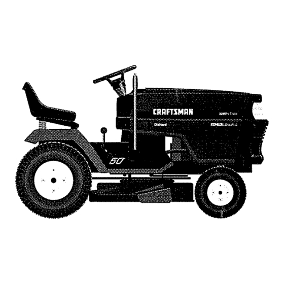
- Page 3 PRODUCT SPECIFICATgONS CONGRATULATIONS on your purchase of a Sears HORSEPOWER: 22 0 Tractor_ It has been designed, engineered and manufac- tured to give you the best possible dependability GASOLINE CAPACFTY 3,5 GALLONS performance. AND TYPE: UNLEADED REGULAR Should you experience any problem you cannot easily OIL TYPE (AP1-SF/SG): SAE 10W-30 (above 32°F)
-
Page 4: Table Of Contents
,U,,lU i ,lunu n u, ,nil TABLE OF CONTENTS , ii,,Ul i U,l,nll ,, iii ......MAINTENANCE SCHEDULE ........SAFETY RULES ............SERVICE AND ADJUSTMENTS ......19-25 PRODUCT SPECIFICATIONS ........STORAG E ..............CUSTOMER RESPONSIBILITIES ..... 3, 15-18 TROUBLESHOOTING ..........28-29 WARRANTY .............. -
Page 5: Accessories
ACCESSORIES AND ATTACH ENT$ These accessories and attachments were available through most Soars rotaif outlets and service centers when the tractor was purchased Most Sears stores can order those items for you when you provide the model number of your tractor. ENGINE MAINTENANCE SPARK PLUG... - Page 6 H,'Hm'= H =='=n CONTENTS HARDWARE ,,,u, nu, m n,== !n ..... ni,,u,n nu, = ,, Parts Bag contents shown full size Parts packed separately in carton =-n 1,, n ÷ Seat Battery acid (1) Shoulder' Bolt 5/16-18 (1) Knob Battery Steering Wheel H 'J (1) Washer...
- Page 7 .... , ..........,,,,,,,,,,,,,,,, ,,, ......ASSEMBLY You r new tractor has been assembled at the factory with the exception of those parts left unassembled for shipping purposes_ To ensure safe and proper operation of your tractor all parts and hardware you assemble must be tightened securely. the correct tools as necessary to insure proper tightness_ TOOLS REQUIRED...
- Page 8 ,lun nl ,,n, IHn H nn nn n i ............HOW TO SET UP YOUR TRACTOR INSTALL SEAT (See Fig. 3) Adjust seat before tightening adjustment knob. PREPARE BATTERY (See Fig. 2) ° Remove cardboard packing on seat pan. Place seat on seat pan and assemble shoulder bolt. CAUTION: Wear eye and face shield.
- Page 9 =,,= ,,,,=,, =-,,=,,-,,=,,,,H ASSEMBLY INSTALL MOWER AND DRIVE BELT Place the suspension arms on inward pointing deck pins.. If necessary, rock and raise front of mower to (See Figs. 4 and 7) align deck pins with the holes in suspension arms°...
- Page 10 ASSEMBLY J i J INSTALL BATTERY (See Figs, 5 and 6) TERMINAL CAUTION: Do not short battery termi- WINGNUTS metal bracelets, wristwatch bands, nals. Before installing battery, remove rings, etc. Positive terminal must be connected first to prevent sparking from acciden- tal grounding.
- Page 11 OPERATION KNOW YOUR TRACTOR READ THIS OWNER'S MANUAL AND SAFETY RULES BEFORE OPERATING YOUR TRACTOR Compare the illustrations with your tractor to familiarize yourself with the locations of various controls and adjustments° Save this manual for future reference. ATTACHMENT CLUTCH SWITCH LtFT LEVER IGNITION SWITCH PLUNGER...
- Page 12 The operation of any tractor can result in foreign objects thrown into the eyes, which can result in severe eye damage. Always wear safety glasses or eye shields while operating your tractor or performing any adjustments or repairs. We recommend a wide vision safety mask for over the spectacles or standard safety glasses.
- Page 13 OPERATnON TO ADJUST GAUGE WHEELS (See Fig. 9) TO OPERATE ON HILLS • Adjust mower to desired cutting height. AUTION: Do not drive up or down Lower mower with tift control Remove rear retainer hills with slopes greater than 15 ° and spring and clevis pin which secure each gauge wheel.
-
Page 14: Storage
....i, ilu OPERATION ADD GASOLINE MOWING TiPS Fill fuel tank+ Use fresh, clean, regular unleaded Tire chains cannot be used when the mower housing gasoline. (Useof leadedgasoinewilincreasecarbon is attached to unit. and lead oxide deposits and reduce valve life). Mower' should be properly leveled for best mowing IMPORTANT: WHEN OPERATING IN TEMPERATURES... - Page 15 CUSTO RESPONS BULmTmES i1,,i ..,ill ,,i,,UllU,iH IM ..MAINTENANCE SCHEDULE .,,____ _/'_*/_" AS YOU COMPLETE "_ _ /i_._'_.'t_ REGULAR _b_'../_ _._._ _-_ £.q_._"_'4_._/'_q_./',_'4_. ,__RVICE DATES SERVICE Check Brake Operation Check Tire Pressure V ....I..Checkfor LooseFasteners SharpentReplaceMower Blades Lubr'oat,oncha,t :: .
- Page 16 ,,i,iii CUSTOIVIE ESPONSnBIL T E$ HH"H TRACTOR ° The blade can be sharpened with a file or on a g rinding wheel.. Do not attempt to sharpen while on the mower. Always observe safety rules when performing any mainte- To check blade balance, you will need a 5/8" diameter nance_ steel bolt, pin, or a cone bafancer.
- Page 17 CUSTOM PON$1BIL BATTERY (See Fig. 16) NOTE: Although multiwiscosity oils (5W30, 10W30 etco) Your tractor has a battery charging system which is suffi- improve starting in cold weather, these multi-viscosity oils will result in increased oil consumption when used above cient for normal use.
- Page 18 ii i,, IH i, m i,l,l,l,,,,ml nH'H "1' CUSTOM RESIPONSAIB LIT ES nlun CLEAN AIR SCREEN (See Fig. 19) CARTRIDGE Air' screen must be kept free of dirt and chaff to prevent engine damage from overheating,. Clean with a wire brush or compressed air to remove dirt and stubborn dried gum COVER fibers.
- Page 19 SERVICE AND ADJUSTMENTS ,, i,iii ..i..i ....ii..M'"'I"''I'I""II"I"I" " CAUTION: BEFORE PERFORMING ANY SERVICE OR ADJUSTMENTS: Depress clutch/brake pedal fully and set parking brake. Place gearshift lever in neutral (N) position, Place attachment clutch in "DISENGAGED" position. Turn ignition key "OFF"...
- Page 20 ADJUSTMENTS TO REPLACE MOWER DRIVE BELT FRONT-TO-BACK ADJUSTMENT (See Figs. 23 and 24) - IMPORTANT: DECK MUST BE LEVEL SIDE-TO-SIDE. MOWER DRIVE BELT REMOVAL (See Fig. 25) - THE FOLLOWING FRONT-TO-SACK ADJUSTMENT • Park tractor on a level surface° Engage parking brake. NECESSARY, BE SURE TO ADJUST BOTH FRONT LINKS EQUALLY SO MOWER WiLL STAY LEVEL SiDE-TO-SIDE Remove four screws from Loll., mandrel cover' and...
- Page 21 m,, ,,i,=lml =,=1== CE AN ADJUSTMENTS ,==,=,, ==, ,= ,H=,, TO REPLACE MOWER BLADE DRIVE BELT .o L. (See Fig. 26) Park the tractor on level surface, Engage parking brake. • Remove mower drive belt (See'q'O REPLACE MOWER DRIVE BELT" in this section of this manual). •...
- Page 22 SERVICE AN ADJUSTMENTS TO REPLACE MOTION DRIVE BELT TO ADJUST STEERING WHEEL ALIGNMENT (See Fig. 29) If steering wheel crossbars are not horizontal (left to right) when wheels are positioned straight forward, remove steer- Park the tractor on level surface.. Engage parking brake° ing wheel and reassemble per instructions in the Assembly For ease of service there is a belt installation guide decal on section of this manual...
-
Page 23: Wiring Diagram
ii i i,,,,11,1,1,1,1,111 $ERVmCE AND AOJU ENT$ iii1,11 REMOVE WHEEL FOR REPAIRS FRONT WHEEL (See Fig° 32) - Btock up axle securely° Remove axle cover, retaining ring andwashersto allow wheel removal. Repair tire and reassemble. "POSITIVE" "NEGATIVE' Replace washers and snap retaining ring securely in axle groove. - Page 24 TO ADJUST ATTACHMENT LIFT SPRING ENGINE (See Fig. 34) ADJUST THROTTLE CONTROL CABLE While holding spring bushing with wrench, loosen jam (See Fig. 36) nut. The throttle control has been preset at the factory and Turn adjustment bolt clockwise to extend spring and adjustment should not be necessary.
- Page 25 SERVUCE ANO ADJUSTMENTS , n,,, i,,,,lUl i ,,,,,,, ,11, FINAL SETTING - Start engine and allow to warm for five minutes.. Make IDLE FUEL ADJUSTING final adjustments with engine running and shift/motion IDLE SPEED NEEDLE ADJUSTING control lever in neutral (N) position. SCREW The high idle is set at the factory and cannot be adjuste&...
- Page 26 STORAGE ENGBNE Immediately prepare your tractor for' storage at the end of the season or' if the tractor will not be used for 30 days or FUEL SYSTEM ... IMPORTANT: iT IS IMPORTANT TO PREVENT GUM CAUTION: Never store the tractor with DEPOSITS FROM FORMING...
-
Page 28: Air Screen
TROUBLESHOO=IING PO NTS ......PROBLEM CAUSE CORRECTION ,i,ilrllii ii ii Will not start Out of fuel Fill fuel tank Engine not "CHOKED" properly see "TO START ENGINE" in Operation section Engine fIooded Wait several minutes before attempting to start Bad spark plug Replace spark plug_ Dirty air filter Clean/replace... -
Page 29: Seat
TROUBLESHOOTING POINTS CORRECTION PROBLEM CAUSE Faulty operator-safety presencecontrol system, Engine continues to run Check wiring, switches and connections.. If not corrected, contact an authorized service center/ when operator leaves seat with attachment clutch department engaged Poor cut - uneven Worn, bent or loose blade Replace blade Tighten blade bolt.
Need help?
Do you have a question about the 917.257740 and is the answer not in the manual?
Questions and answers