
Related Manuals for Simrad FU80


Summary of Contents for Simrad FU80
-
Page 1: User Guide
FU80, NF80, QS80 User Guide ENGLISH www.simrad-yachting.com pro.simrad-yachting.com... - Page 2 Copyright Copyright © 2011 Navico Holding AS. Warranty The warranty card is supplied as a separate document. In case of any queries, refer to the brand web site of your display or system: pro.simrad-yachting.com www.simrad-yachting.com...
-
Page 3: Table Of Contents
Basic operation - all remotes Using the NF80 Using the FU80 Using the QS80 Changing commanded rudder direction Alarms Restoring factory settings Maintenance Changing default settings The main menu Specifications Technical specifications Drawings Contents | FU80, NF80, QS80 User Guide... -
Page 4: Introduction
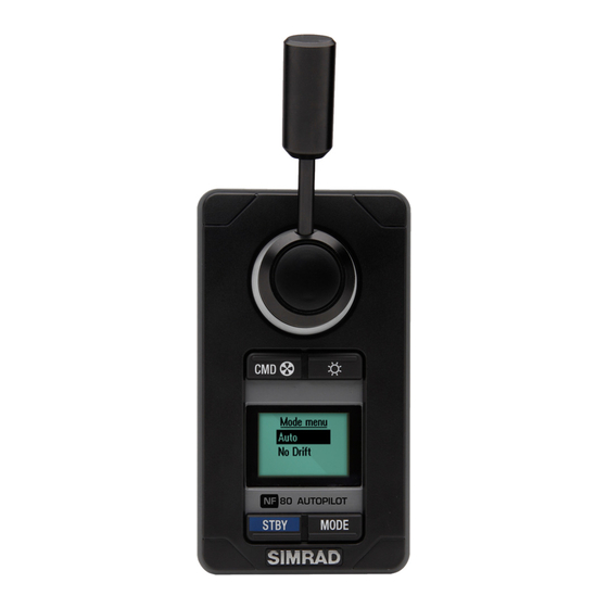
Introduction About this manual This manual describes how to install and use the FU80, NF80 and the QS80 remotes. NF80 FU80 QS80 These remotes can be used to remotely control the AP70, AP80, AP24 and AP28 autopilot systems. They can also be used to remotely operate the autopilot function in NSE, NSS and NSO (Simrad Multifunction Displays). -
Page 5: Parts Included
Key Description Remote unit, including 6 m (19.7 ft) Micro-C drop cable Gasket for panel sealing Screws and accessories Long type lever (FU80 and NF80) Micro-C T-connector User manual Mounting template Warranty card Introduction |... -
Page 6: Installation
Peel backing off the gasket (A) and apply it to the remote or to the mounting surface Place the remote into the console Secure the unit with the 4 screws (B) Clip the bezel (C) in place Installation | FU80, NF80, QS80 User Guide... - Page 7 The lever is not mounted from factory. Screw the lever firmly into the mounting hole. The FU80 lever The factory mounted short lever can be replaced by the longer lever included in the package. Installation | FU80, NF80, QS80 User Guide...
-
Page 8: Wiring
Included with the unit Micro-C T-connector For part CAN-bus backbone numbers, refer to our web site. Simnet to Micro-C (female) cable. 0.5 m (1.64 ft) SimNet T-joiner (3p) or SimNet Multijoiner (7p) SimNet backbone Installation | FU80, NF80, QS80 User Guide... -
Page 9: Operation
Softkey Function OK/Accept/Acknowledge alarm STBY MODE STBY MODE Cancel/Return to previous menu level Mute alarm STBY MODE STBY MODE Move upwards in menu STBY MODE Move downwards in menu Operation | FU80, NF80, QS80 User Guide... -
Page 10: The Screen
The remote’s operational state is indicated with icons. Icon Status Description None Active In operation The autopilot is operated from another control Passive unit The autopilot is operated from another control Locked device and this device is locked Operation | FU80, NF80, QS80 User Guide... - Page 11 Active thrusters are indicated with thruster icon in the display. ¼ Note: Only available in AP70/AP80 systems. The thrusters must be available for autopilot steering in active steering profile. Operation | FU80, NF80, QS80 User Guide...
-
Page 12: Using The Nf80
No action (warning sound and information dialog) Wind ¼ Note: The Wind mode is only available if the autopilot system has been set up for sailboat. See the Installation manual for your autopilot system. 10 | Operation | FU80, NF80, QS80 User Guide... -
Page 13: Mode Selection
NoDrift mode. The value will change 1° each time the lever is pressed to left or right. If you keep the lever pressed, the value automatically changes at a rate of 5° per second. Each beep indicates a 1° change. | 11 Operation | FU80, NF80, QS80 User Guide... -
Page 14: Using The Fu80
You can use the FU80 in FU, AUTO and NoDrift mode. You can also get command if the system is in NFU, NAV or Wind mode, but you cannot operate these modes from the FU80. - Page 15 Use the lever to change set heading in AUTO mode and the set course in NoDrift mode. The value will change in steps defined by lever rotation, starting from 0.5°/second at 3° lever rotation, up to 5°/second at max lever rotation. | 13 Operation | FU80, NF80, QS80 User Guide...
-
Page 16: Using The Qs80
Centering the rudder A single downwards press on the stick while in Standby or NFU mode will command the rudder to mid-position. A short beep will sound when the rudder is centered. 14 | Operation | FU80, NF80, QS80 User Guide... - Page 17 1° each time the stick is pressed to left or right. If you keep the stick pressed, the value automatically changes at a rate of 5° per second. Each beep indicates a 1° heading/course change. | 15 Operation | FU80, NF80, QS80 User Guide...
-
Page 18: Changing Commanded Rudder Direction
Changing commanded rudder direction By default, the rudder moves in the same direction as the lever on FU80 and NF80. When you press the lever to port, the rudder is directed to port. If the lever is rotated 180° on FU80, or if FU80/NF80 are mounted facing aft, the rudder movement can be inverted to maintain a rudder command that coincide with the lever movement. -
Page 19: Restoring Factory Settings
If the unit requires any form of cleaning, use fresh water and a mild soap solution (not a detergent). It is important to avoid using chemical cleaners and hydrocarbons such as diesel, petrol, etc. | 17 Operation | FU80, NF80, QS80 User Guide... -
Page 20: Changing Default Settings
Units Inverse display Damping Contrast Station Only available on FU80 and NF80. • Local settings: Gives access to settings that applies to this unit. • SimNet group: Assigns this unit to a SimNet group. You remove the menu and return to standard display by pressing... -
Page 21: Specifications
Back: Plastic cover Temperature -25° C to + 55° C (-13° F to +131° F) Weight NF80, FU80: 0.5 kg (1,10 lbs) QS80: 0.4 kg (0,88 lbs) Environmental Weather IEC 60945 sec. 8.8, exposed, front when desk mounted or bulkhead mounted with optional frame. -
Page 22: Drawings
Drawings Dimension, Remotes 66 mm (2.60") 40 mm (1.55") 80 mm (3.15") 66 mm (2.60") NF80 QS80 FU80 51 mm (1.98") 63 mm (2.46") 16 mm (0.63") 63 mm (2.46") 20 | Specifications | FU80, NF80, QS80 User Guide... - Page 23 40 mm (1.55") 80 mm (3.15") 66 mm (2.60") Connector pin-out Color Function Shield NET-S (Power source +) Black NET-C (Power source -) White NET-H (CAN high) Blue NET-L (CAN low) | 21 Specifications | FU80, NF80, QS80 User Guide...
Need help?
Do you have a question about the FU80 and is the answer not in the manual?
Questions and answers