Table of Contents

Subscribe to Our Youtube Channel
Related Manuals for EuroLite LED TMH-30 MK2 Moving-Head Spot


Summary of Contents for EuroLite LED TMH-30 MK2 Moving-Head Spot
- Page 1 BEDIENUNGSANLEITUNG USER MANUAL LED TMH-30 MK2 Moving-Head Spot Für weiteren Gebrauch aufbewahren! © Copyright Keep this manual for future needs! Nachdruck verboten! Reproduction prohibited!
-
Page 2: Table Of Contents
Diese Bedienungsanleitung gilt für die Artikelnummer 51785981 This user manual is valid for the article number 51785981 Das neueste Update dieser Bedienungsanleitung finden Sie im Internet unter: You can find the latest update of this user manual in the Internet under: www.eurolite.de 2/35 00088984.DOC, Version 1.0... -
Page 3: Einführung
- sich die letzte Version der Anleitung im Internet herunter laden EINFÜHRUNG Wir freuen uns, dass Sie sich für einen EUROLITE LED TMH-30 MK2 entschieden haben Wenn Sie nachfolgende Hinweise beachten, sind wir sicher, dass Sie lange Zeit Freude an Ihrem Kauf haben werden. - Page 4 Das Gerät darf nicht in Betrieb genommen werden, nachdem es von einem kalten in einen warmen Raum gebracht wurde. Das dabei entstehende Kondenswasser kann unter Umständen Ihr Gerät zerstören. Lassen Sie das Gerät solange uneingeschaltet, bis es Zimmertemperatur erreicht hat! Bitte überprüfen Sie vor der ersten Inbetriebnahme, ob kein offensichtlicher Transportschaden vorliegt.
-
Page 5: Bestimmungsgemäße Verwendung
Kinder und Laien vom Gerät fern halten! Das Gerät darf niemals unbeaufsichtigt betrieben werden! BESTIMMUNGSGEMÄßE VERWENDUNG Bei diesem Gerät handelt es sich um einen kopfbewegten LED-Effektstrahler, mit dem sich dekorative Lichteffekte erzeugen lassen. Dieses Produkt ist für den Anschluss an 100-240 V, 50/60 Hz Wechselspannung zugelassen und wurde ausschließlich zur Verwendung in Innenräumen konzipiert. -
Page 6: Gerätebeschreibung
Die maximale Umgebungstemperatur T = 45° C darf niemals überschritten werden. Nehmen Sie das Gerät erst in Betrieb, nachdem Sie sich mit seinen Funktionen vertraut gemacht haben. Lassen Sie das Gerät nicht von Personen bedienen, die sich nicht mit dem Gerät auskennen. Wenn Geräte nicht mehr korrekt funktionieren, ist das meist das Ergebnis von unfachmännischer Bedienung! Soll das Gerät transportiert werden, verwenden Sie bitte die Originalverpackung, um Transportschäden zu vermeiden. -
Page 7: Geräteübersicht
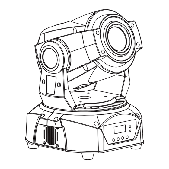
Geräteübersicht (1) Projektorkopf (2) Linse (3) Gehäuseschraube (4) Projektorarm (5) Base (6) Tragegriff (7) Mikrofon (8) DMX-Anzeige (9) Gummifuß (10) Steuereinheit (11) Mode/Esc-Taste (12) Up-Taste (13) Down-Taste (14) Enter-Taste (15) Display (16) Sicherungshalter (17) Netzanschluss (18) DMX-Eingangsbuchse (19) DMX-Ausgangsbuchse (20) Lüftergitter 7/35 00088984.DOC, Version 1.0... -
Page 8: Installation
INSTALLATION Projektormontage Die Aufhängevorrichtungen des Projektors muss so gebaut und bemessen sein, dass sie 1 Stunde lang ohne dauernde schädliche Deformierung das 10-fache der Nutzlast aushalten kann. Die Installation muss immer mit einer zweiten, unabhängigen Aufhängung, z. B. einem geeigneten Fangnetz, erfolgen. - Page 9 ACHTUNG! Montieren Sie den Projektor ausschließlich über zwei geeignete Haken. Achten Sie darauf, dass das Gerät sicher befestigt wird. Vergewissern Sie sich, dass die Verankerung stabil ist. Das Gerät kann direkt auf den Boden gestellt werden oder in jeder möglichen Position im Trussing installiert werden, ohne seine funktionellen Eigenschaften zu verändern.
-
Page 10: Anschluss An Den Dmx-512 Controller / Verbindung Projektor - Projektor
Anschluss an den DMX-512 Controller / Verbindung Projektor – Projektor Achten Sie darauf, dass die Adern der Datenleitung an keiner Stelle miteinander in Kontakt treten. Die Geräte werden ansonsten nicht bzw. nicht korrekt funktionieren. Beachten Sie, dass die Startadresse abhängig vom verwendeten Controller ist. Unbedingt Bedienungsanleitung des verwendeten Controllers beachten. -
Page 11: Bedienung
BEDIENUNG Wenn Sie das Gerät an die Spannungsversorgung angeschlossen haben, nimmt der LED TMH-30 MK2 den Betrieb auf. Während des Reset justieren sich die Motoren aus und das Gerät ist danach betriebsbereit. Stand Alone-Betrieb Der LED TMH-30 MK2 lässt sich im Stand Alone-Betrieb ohne Controller einsetzen. Trennen Sie dazu den LED TMH-30 MK2 vom Controller und rufen Sie das vorprogrammierte Programm, wie im Kapitel Control Board beschrieben, auf. - Page 12 12/35 00088984.DOC, Version 1.0...
-
Page 13: Dmx-Gesteuerter Betrieb
DMX-gesteuerter Betrieb Über Ihren DMX-Controller können Sie die einzelnen Geräte individuell ansteuern. Das Gerät verfügt über drei verschiedene DMX-Kanal-Modi. Dabei hat jeder DMX-Kanal eine andere Belegung mit verschiedenen Eigenschaften. Die einzelnen DMX- Kanäle und ihre Eigenschaften sind unter DMX-Protokoll aufgeführt. Adressierung des Projektors Über das Control Board können Sie die DMX-Startadresse definieren. - Page 14 Steuerkanal 3 - Geschwindigkeit PAN-/TILT-Bewegung Decimal Hexad. Percentage S/F Eigenschaft 0 255 00 FF 0% 100% F Abnehmende Geschwindigkeit Steuerkanal 4 - Farbrad Lineare Farbänderung gemäß der Bewegung des Reglers. Sie können den Farbwechsler an jeder gewünschten Position anhalten. Decimal Hexad. Percentage S/F Eigenschaft 0 15 00 0F...
- Page 15 56 62 38 3E 22% 24% S Gobo 8 63 69 3F 45 25% 27% F Gobo 8 Shake mit zunehmender Geschwindigkeit 70 76 46 4C 27% 30% F Gobo 7 Shake mit zunehmender Geschwindigkeit 77 83 4D 53 30% 33% F Gobo 6 Shake mit zunehmender Geschwindigkeit 84 90 54 5A...
-
Page 16: 11-Dmx-Kanal-Modus
11-DMX-Kanal-Modus Steuerkanal 1 - Horizontale Bewegung (PAN) Wenn Sie den Regler verschieben, bewegen Sie den Kopf horizontal (PAN). Allmähliches Einstellen des Kopfes bei langsamen Schieben des Reglers (0-255, 128-Mitte). Der Kopf kann an jeder gewünschten Einstellung angehalten werden. Steuerkanal 2 - Vertikale Bewegung (TILT) Wenn Sie den Regler verschieben, bewegen Sie den Kopf vertikal (TILT). - Page 17 21 27 15 1B 8% 11% S Gobo 3 28 34 1C 22 11% 13% S Gobo 4 35 41 23 29 14% 16% S Gobo 5 42 48 2A 30 16% 19% S Gobo 6 49 55 31 37 19% 22% S Gobo 7 56 62...
-
Page 18: 2-Dmx-Kanal-Modus
2-DMX-Kanal-Modus Steuerkanal 1 - Interne Programme Decimal Hexad. Percentage S/F Eigenschaft 0 15 00 0F 0% 6% S Blackout 16 75 10 4B 6% 29% S Internes Programm langsame Geschwindigkeit 76 135 4C 87 30% 53% S Internes Programm mittlere Geschwindigkeit 136 195 88 C3 53% 76%... -
Page 19: Sicherungswechsel
Sicherungswechsel Wenn die Feinsicherung des Gerätes defekt ist, darf diese nur durch eine Sicherung gleichen Typs ersetzt werden. Vor dem Sicherungswechsel ist das Gerät allpolig von der Netzspannung zu trennen (Netzstecker ziehen). Vorgehensweise: Schritt 1: Öffnen Sie den Sicherungshalter an der Geräterückseite mit einem passenden Schrauben- dreher. -
Page 20: Introduction
- download the latest version of the user manual from the Internet INTRODUCTION Thank you for having chosen a EUROLITE LED TMH-30 MK2. If you follow the instructions given in this manual, we are sure that you will enjoy this device for a long period of time. - Page 21 If the device has been exposed to drastic temperature fluctuation (e.g. after transportation), do not switch it on immediately. The arising condensation water might damage your device. Leave the device switched off until it has reached room temperature. Please make sure that there are no obvious transport damages. Should you notice any damages on the A/C connection cable or on the casing, do not take the device into operation and immediately consult your local dealer.
-
Page 22: Operating Determinations
OPERATING DETERMINATIONS This device is a LED moving-head lighting effect for creating decorative effects. This product is allowed to be operated with an alternating voltage of 100-240 V, 50/60 Hz and was designed for indoor use only. This device is designed for professional use, e.g. on stages, in discotheques, theatres etc. Lighting effects are not designed for permanent operation. -
Page 23: Description Of The Device
DESCRIPTION OF THE DEVICE Features Versatile LED Head Spot with 30 W LED • Compact lightweight • 14, 11 or 2 DMX channels selectable • Equipped with a 30 W COB LED • 7 brilliant, dichroic colors plus white • Rainbow effect with adjustable speed in both directions •... -
Page 24: Installation
(16) Fuseholder (17) Power supply (18) DMX-In socket (19) DMX-Out socket (20) Ventilation grille INSTALLATION Rigging The installation of the projector has to be built and constructed in a way that it can hold 10 times the weight for 1 hour without any harming deformation. The installation must always be secured with a secondary safety attachment, e.g. - Page 25 installation material and the projector. If you lack these qualifications, do not attempt the installation yourself, but instead use a professional structural rigger. Improper installation can result in bodily injury and.or damage to property. The projector has to be installed out of the reach of people. If the projector shall be lowered from the ceiling or high joists, professional trussing systems have to be used.
-
Page 26: Dmx-512 Connection / Connection Between Fixtures
DMX-512 connection / connection between fixtures The wires must not come into contact with each other, otherwise the fixtures will not work at all, or will not work properly. Please note, the starting address depends upon which controller is being used. Only use a DMX-cable and 3-pin XLR-plugs and connectors in order to connect the controller with the fixture or one fixture with another. -
Page 27: Operation
OPERATION After you connected the effect to the mains, the EUROLITE LED TMH-30 MK2 starts running. During the Reset, the motors are trimmed and the device is ready for use afterwards. Stand Alone operation In the Stand Alone mode, the LED TMH-30 MK2 can be used without controller. - Page 28 28/35 00088984.DOC, Version 1.0...
-
Page 29: Dmx-Controlled Operation
DMX-controlled operation You can control the projectors individually via your DMX-controller. The device has three different DMX channel modes. Every DMX-channel has a different occupation with different features. The individual channels and their features are listed under DMX-protocol. Addressing The Control Board allows you to assign the DMX starting address, which is defined as the first channel from which the LED TMH-30 MK2 will respond to the controller. - Page 30 Control-channel 3 - PAN/TILT-speed Decimal Hexad. Percentage S/F Feature 0 255 00 FF 0% 100% F Decreasing speed Control-channel 4 - Color-wheel Linear color change following the movement of the slider. In this way you can stop the color-wheel in any position.
- Page 31 70 76 46 4C 27% 30% F Gobo 7 shake with increasing speed 77 83 4D 53 30% 33% F Gobo 6 shake with increasing speed 84 90 54 5A 33% 35% F Gobo 5 shake with increasing speed 91 97 5B 61 36% 38% F Gobo 4 shake with increasing speed...
-
Page 32: 11 Dmx Channel Mode
11 DMX channel mode Control-channel 1 - Horizontal movement (PAN) Push slider up in order to move the head horizontally (PAN). Gradual head adjustment from one end of the slider to the other (0-255, 128-center). The head can be stopped at any position you wish. Control-channel 2 - Vertical movement (TILT) Push slider up in order to move the head vertically (TILT). - Page 33 28 34 1C 22 11% 13% S Gobo 4 35 41 23 29 14% 16% S Gobo 5 42 48 2A 30 16% 19% S Gobo 6 49 55 31 37 19% 22% S Gobo 7 56 62 38 3E 22% 24% S Gobo 8 63 69...
-
Page 34: Dmx Channel Mode
2 DMX channel mode Control-channel 1 - Internal programs Decimal Hexad. Percentage S/F Feature 0 15 00 0F 0% 6% S Blackout 16 75 10 4B 6% 29% S Internal program low speed 76 135 4C 87 30% 53% S Internal program medium speed 136 195 88 C3 53% 76%... -
Page 35: Replacing The Fuse
Replacing the fuse If the fine-wire fuse of the device fuses, only replace the fuse by a fuse of same type and rating. Before replacing the fuse, unplug mains lead. Procedure: Step 1: Open the fuseholder on the rear panel with a fitting screwdriver. Step 2: Remove the old fuse from the fuseholder.
Need help?
Do you have a question about the LED TMH-30 MK2 Moving-Head Spot and is the answer not in the manual?
Questions and answers