Advertisement
Quick Links
V1
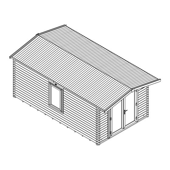
AVON PVC 3.0m x 5.0m ( 45mm ) Log Cabin
E10-3050APVC-45
Installation Manual
Please read this installation manual carefully
before proceeding with the construction of your log cabin.
Check all components prior to assembly
If you have purchased a log cabin with an extension please refer to the extension manual set
Important!
All dimensions are approximate and subject to the limitations of the materials used and the methods of manufacture
Unique Cabin Reference Number
Construction videos link
_____________________________
www.dunsterhouse.co.uk
Advertisement

Related Manuals for Dunster House E10-3050APVC-45


Summary of Contents for Dunster House E10-3050APVC-45
- Page 1 AVON PVC 3.0m x 5.0m ( 45mm ) Log Cabin E10-3050APVC-45 Installation Manual Please read this installation manual carefully before proceeding with the construction of your log cabin. Check all components prior to assembly If you have purchased a log cabin with an extension please refer to the extension manual set...
- Page 2 Parts List - BLC Page 2 WOODEN PARTS : including 1 extra wall log, 1 extra floor board and 2 extra roof boards PART NUMBER DESCRIPTION THK_mm WIDTH_mm LNG_mm EN.2850 Bearer ( Pressure treated ) 2850 F.4760 Floor Board T&G 4760 F.1590 1590...
- Page 3 Parts List - UK Page 3 UPVC DOORS PART NUMBER DESCRIPTION FD1WL1628x1893 uPVC French Doors SGUFD1WL559x1567 Door Glass 28x559x1567 UPVC WINDOWS PART NUMBER DESCRIPTION W3WL738x1158 uPVC Window SGUW3WL532x952 Window Glass 28x532x952...
- Page 4 • Dunster House Ltd will not freely replace any parts that are damaged due to any neglectful workmanship when your cabin is being built. However, replacement parts are available to purchase, please contact our Parts department at parts@dunsterhouse.co.uk.
- Page 5 If you are still unable to find an answer to your query please contact our Customer Services department by email or in writing stating your query and including your order number starting with "SO" or your postcode to either: cs@dunsterhouse.co.uk or FAO Customer Services, Dunster House Ltd - Factory 1, Elms Farm Industrial Estate, Bedford, MK41 0LF Assembly Instruction Instructions are available from our website - https://dunsterhouse.co.uk/customer-login-area/log-in.
- Page 6 Page 6 How to install twisted/warped timber Timber is a natural product and unlike extrusions made from plastic or metal is likely to twist due to the nature of the material. Warped timber is unavoidable particularly with soft wood and is more common in longer and larger sections. Warping can occur even once a product is packed.
- Page 7 Component List Page 7 BEARERS BOTTOM WALL LOG Pressure Treated ITEM QTY PART NUMBER DESCRIPTION THK_mm WIDTH_mm LNG_mm ITEM QTY PART NUMBER DESCRIPTION THK_mm WIDTH_mm LNG_mm EN.2850 Bearer ( Pressure treated ) 2850 B45.655.70.0.0 Bottom Wall Log 64.5 BOTTOM WALL LOG WALL LOG ITEM QTY PART NUMBER...
-
Page 8: Component List
Component List Page 8 WALL LOG ITEM QTY PART NUMBER DESCRIPTION THK_mm WIDTH_mm LNG_mm A45.5240.70.320.0 Wall Log 5240 TOP WALL LOG - Right ITEM QTY PART NUMBER DESCRIPTION THK_mm WIDTH_mm LNG_mm XN45.11R.5490.70.570.0 Top Wall Log Right 5490 TOP WALL LOG - Left ITEM QTY PART NUMBER DESCRIPTION... - Page 9 Component List Page 9 PURLIN Reinforced Middle ITEM QTY PART NUMBER DESCRIPTION THK_mm LNG_mm P45.5490.65.565.0 Purlin and Purlin Support 5490 PURLIN Reinforced Left ITEM QTY PART NUMBER DESCRIPTION THK_mm LNG_mm P45.5490.65.565.0 Purlin and Purlin Support 5490 PURLIN Reinforced Right ITEM QTY PART NUMBER DESCRIPTION THK_mm...
- Page 10 Component List Page 10 Bearer Layout for Log Cabin The minimum overall base dimension should be 100mm bigger than the external dimensions of the cabin. Only a completely level and stable load bearing foundation should be used as a base for your log cabin. Failure to do this may lead to installation issues and diminish the integrity of your log cabin. Screw the 2 outer bearers together with 50mm screws at 400mm intervals leaving a 25mm interval at the either end of the bearers.
- Page 11 First Wall Logs Page 11 ITEM QTY PART NUMBER DESCRIPTION IMPORTANT - Ensure that the base of the bearers and first layer of EN.2850 Bearer ( Pressure treated ) wall logs are level and square. Continue to check if the cabin is A45.4990.70.70.0 Wall Log square by measuring the diagonals and that the walls are level...
-
Page 12: Front Wall
Wall Layout Page 12 The layout of your doors and windows can be changed by installing the relevant logs on the opposite side of the cabin or the Front Wall opposite side of the front wall. The position of the XN logs cannot be changed and need to have the top angle sloping outwards from the middle of the cabin. - Page 13 Wall Layout Page 13 The layout of your doors and windows can be changed by installing the relevant logs on the opposite side of the cabin or Side Wall - Left the opposite side of the front wall. The position of the XN logs cannot be changed and need to have the top angle sloping outwards from the middle of the cabin.
- Page 14 Doors & Windows Page 14 ITEM QTY PART NUMBER The windows are pre-assembled but the door frame for your cabin comes E10 - DOUBLE DOOR UPVC FRAME - 45 in separate parts to protect it during transportation. Please note that the STANDARD UPVC WINDOW (FRAME) - 45mm bottom part will be slotted together with the top part to prevent damage during transport.
- Page 15 Do not tighten the screw fully, this will allow the frames enough freedom of movement to realign vertically but stay in position horizontally. Attach the Dunster House logo plate to hide the screw and slotted hole when the frame is fitted.
- Page 16 Page 16 Glazing Windows and Doors Sealed units are approximately 10mm smaller in length and width than the aperture. This difference in size will be packed using bridge packers (4mm), black shims (2mm), and green shims (1mm). Bridge packers must be used only against the frame, while shims are to be used only next to sealed units.
- Page 17 Page 17 Glazing Windows and Doors 5. After packing the sealed units correctly, refit the beads in the same position as you removed them; start with the smallest lengths first before inserting the longer lengths. Carefully use a nylon or non-marking rubber mallet to help tap the beads into position, starting at the ends.
- Page 18 Removing uPVC Door & Window Glazing Beads Page 18 Removing the uPVC glazing beads uPVC Door from the frames. Frame Views looking from uPVC Secondary the inside of the door Sash & window uPVC Lead Sash uPVC Glazing Beads uPVC Glazing Beads uPVC Glazing Beads...
- Page 19 Installing uPVC Doors and Window with uPVC Frames Page 19 Firstly, remove the uPVC glazing beads from both of the doors and window (refer to previous page). PLEASE NOTE - The images used are for reference only. The The glass, uPVC glazing beads and timber trims are to be put to one side for the moment. number and configuration of your windows and doors may differ The following principles apply for both doors and window.
- Page 20 uPVC Door and Window Glass Assembly Page 20 Place the glass in the window and door frames. Secure them inside with the beading, using a rubber mallet. Once installed, a bead of silicone will be required on both the internal and external side of the Upvc frames to make it watertight.
- Page 21 Door and Window Frame Trims Page 21 ITEM QTY PART NUMBER DESCRIPTION Views from inside the 19x22x705 GT Timber Window Frame Gasket Trim 19x22x1123 GT Timber Window Frame Gasket Trim Cabin 20x23x725 DRIP TRIM Drip Trim 19x22x1595 GT Timber Door Frame Gasket Trim 19x22x1595 GT 19x22x1865 GT Timber Door Frame Gasket Trim...
- Page 22 Top Wall Logs Page 22 ITEM QTY PART NUMBER DESCRIPTION IMPORTANT - Check the cabin is square and the walls are level. A45.2990.70.70.0 Wall Log A45.655.70.0.0 Wall Log IMPORTANT - Use a step ladder to install the top wall logs, and A45.5240.70.320.0 Wall Log AP45.2990.A...
- Page 23 Purlins Page 23 ITEM QTY PART NUMBER DESCRIPTION THK_mm WIDTH_mm LNG_mm IMPORTANT - Check the cabin is square and the walls are level. P45.5490.65.565.0 Purlin and Purlin Support 5490 IMPORTANT - Use a step ladder to install the purlins and roof boards. Do not put your weight on the roof before all roof boards are secured.
-
Page 24: Roof Installation
Roof Installation Page 24 ITEM QTY PART NUMBER DESCRIPTION IMPORTANT - The optional Roof Insulation is installed after the roof boards, F.1590 Roof Board T&G please refer to the "Roof Insulation (optional)" section in this manual. J.1960 Trim ROOF BOARDS Roof Boards - F •... - Page 25 Page 25 ITEM QTY PART NUMBER THK_mm WIDTH_mm LNG_mm Install roof insulation on top of the roof boards, but ROOF INSULATION P2-PANEL A 2500x1250 1250 2500 prior to installing felt or shingles. Pre-drill 3mm Roof Insulation L Bracket pilot holes for all screws to avoid splitting Roof Insulation Bracket 20mm Screw timbers.
- Page 26 Roof Felt Page 26 Waterproof membrane Roof felt IMPORTANT - Roof Insulation should be installed prior to felt. See the Roof Insulation page for details. 40-50mm overhang • The Eaves Edging and Eaves Edge Reinforcement must be fitted before the waterproof membrane Eaves Roof boards edging...
- Page 27 Shingles (Rectangular) Page 27 Fig. A First layer of rectangular shingles, with the slots Cutting line IMPORTANT - Roof Insulation should be installed prior to pointing towards the roof ridge Fig. D Rectangular Shingles shingles. See the Roof Insulation page for details. •...
- Page 28 Roof Installation Page 28 ITEM QTY PART NUMBER DESCRIPTION It is essential you fit a waterproof covering to the roof. Eaves Edging HN.3000 Eaves Edging is fitted before any roof covering, the Fascia Boards after. Before ZN.1660.C11 Fascia Board following the next steps, please read the "Felt installation" or J.1960 Trim "Shingles installation"...
- Page 29 Storm Braces and Vents Page 29 ITEM QTY PART NUMBER DESCRIPTION THK_mm WIDTH_mm LNG_mm STORM BRACES J.1960.B Storm Brace 1960 • Storm braces should be installed after the roof is fitted. VENTS - SET Vent Set • Storm braces can be installed internally or externally. •...
-
Page 30: Floor Installation
Floor Installation Page 30 ITEM QTY PART NUMBER DESCRIPTION THK_mm WIDTH_mm LNG_mm FLOOR BOARDS J.1960 Trim 1960 F.4760 Floor Board T&G 4760 • We recommend that the floor boards are installed when the cabin walls and roof are completed. • Place the floor boards centrally between the front and rear walls and Floor Boards - F at right angles to the bearers.
Need help?
Do you have a question about the E10-3050APVC-45 and is the answer not in the manual?
Questions and answers