
Subscribe to Our Youtube Channel
Related Manuals for GORMAN-RUPP 14A22-B


Summary of Contents for GORMAN-RUPP 14A22-B
- Page 1 OM‐00661‐04 June 16, 1994 Rev. C 06‐24‐14 INSTALLATION, OPERATION, AND MAINTENANCE MANUAL WITH PARTS LIST 10 SERIES PUMP MODEL 14A22-B GORMAN‐RUPP PUMPS www.grpumps.com 1994 Gorman‐Rupp Pumps Printed in U.S.A.
- Page 2 Register your new Gorman‐Rupp pump online at www.grpumps.com Valid serial number and e‐mail address required. RECORD YOUR PUMP MODEL AND SERIAL NUMBER Please record your pump model and serial number in the spaces provided below. Your Gorman‐Rupp distributor needs this information when you require parts or service. Pump Model: Serial Number:...
-
Page 3: Table Of Contents
TABLE OF CONTENTS INTRODUCTION ..........PAGE I - 1 SAFETY ‐... - Page 4 TABLE OF CONTENTS (continued) TROUBLESHOOTING - SECTION D ......PAGE D - 1 PREVENTIVE MAINTENANCE .
-
Page 5: Introduction
10 SERIES OM-00661 INTRODUCTION Thank You for purchasing a Gorman‐Rupp pump. The following are used to alert maintenance per Read this manual carefully to learn how to safely sonnel to procedures which require special atten install and operate your pump. Failure to do so tion, to those which could damage equipment, and could result in personal injury or damage to the to those which could be dangerous to personnel:... -
Page 6: Safety - Section A
10 SERIES OM-00661 SAFETY ‐ SECTION A This information applies to 10 Series ba 5. Close the suction and discharge sic pumps. Gorman‐Rupp has no con valves. trol over or particular knowledge of the 6. Vent the pump slowly and cau power source which will be used. - Page 7 OM-00661 10 SERIES This pump is designed to pump materi Do not remove plates, covers, gauges, als which could cause serious illness or pipe plugs, or fittings from an over injury through direct exposure or heated pump. Vapor pressure within the emitted fumes.
-
Page 8: Installation - Section B
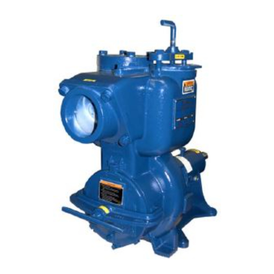
See Figure 1 for the approximate physical dimen configuration, and priming must be tailored to the sions of this pump. OUTLINE DRAWING Figure 1. Pump Model 14A22-B INSTALLATION PAGE B - 1... -
Page 9: Preinstallation Inspection
OM-00661 10 SERIES PREINSTALLATION INSPECTION POSITIONING PUMP The pump assembly was inspected and tested be fore shipment from the factory. Before installation, inspect the pump for damage which may have oc curred during shipment. Check as follows: Death or serious personal injury and damage to the pump or components a. -
Page 10: Suction And Discharge Piping
10 SERIES OM-00661 Installation closer to the pump may result in erratic SUCTION AND DISCHARGE PIPING readings. SUCTION LINES Pump performance is adversely effected by in creased suction lift, discharge elevation, and fric To avoid air pockets which could affect pump prim tion losses. -
Page 11: Suction Lines In Sumps
OM-00661 10 SERIES Suction Lines In Sumps of one or both pumps. To avoid this, position the suction inlets so that they are separated by a dis If a single suction line is installed in a sump, it tance equal to at least 3 times the diameter of the should be positioned away from the wall of the suction pipe. -
Page 12: Discharge Lines
10 SERIES OM-00661 ameter to minimize the chance of plugging. DISCHARGE LINES Siphoning In low discharge head applications (less than 30 feet (9,1 m)), it is recommended that the bypass Do not terminate the discharge line at a level lower line be run back to the wet well, and located 6 than that of the liquid being pumped unless a si... -
Page 13: Automatic Air Release Valve
OM-00661 10 SERIES be a full‐opening, ball‐type valve to pre moving the plug to prevent injury to per vent plugging by solids. sonnel from hot liquid. AUTOMATIC AIR RELEASE VALVE When properly installed, a Gorman‐Rupp Auto matic Air Release Valve will permit air to escape through the bypass line and then close automati... -
Page 14: Alignment
10 SERIES OM-00661 DISCHARGE PIPE CLEAN‐OUT COVER INSTALL AIR RELEASE VALVE IN HORIZONTAL POSITION DISCHARGE CHECK VALVE 90_ LONG RADIUS ELBOW SUPPORT PUMP DISCHARGE BRACKET SELF‐PRIMING CENTRIFUGAL PUMP BLEED LINE 1” (25,4 MM) DIA. MIN. (CUSTOMER FUR NISHED) DO NOT EX SUCTION TEND BELOW PUMP LINE... -
Page 15: Coupled Drives
OM-00661 10 SERIES when the hubs are the same distance apart at all points (see Figure 4B). Check parallel adjustment by laying a straightedge Adjusting the alignment in one direction across both coupling rims at the top, bottom, and may alter the alignment in another direc side. -
Page 16: V-Belt Tensioning
10 SERIES OM-00661 The ratio of deflection to belt span is 1:64 for both parts can catch clothing, fingers, or tools, causing severe injury to person ASA and metric units. Therefore, a belt with a span nel. of 64 inches would require a deflection of 1 inch at the force shown on the Tables for your particular V‐BELT TENSIONING application. - Page 17 OM-00661 10 SERIES Table 1. Sheave Diameter (Inches) Table 2. Sheave Diameter (Millimeters) Deflection Force (Lbs.) Deflection Force (KG.) Belt Deflection Force Belt Deflection Force Uncogged Cogged Uncogged Cogged Hy‐T Belts & Torque‐Flex Hy‐T Belts & Torque‐Flex Uncogged & Machined Uncogged &...
-
Page 18: Operation - Section C
OM-00661 10 SERIES OPERATION - SECTION C Review all SAFETY information in Section A. Add liquid to the pump casing when: 1. The pump is being put into service for the Follow the instructions on all tags, labels and first time. decals attached to the pump. -
Page 19: Operation
OM-00661 10 SERIES Consult the operating manual furnished with the Leakage pump power source before attempting to start the No leakage should be visible at pump mating sur power source. faces, or at pump connections or fittings. Keep all line connections and fittings tight to maintain maxi If an electric motor is used to drive the pump, re... -
Page 20: Stopping
OM-00661 10 SERIES Block the suction line and start the pump. At oper normal for bearings, and they can operate safely to ating speed the pump should pull a vacuum of 20 at least 180_F (82_C). inches (508,0 mm) or more of mercury. If it does Checking bearing temperatures by hand is inaccu... - Page 21 10 SERIES OM-00661 TROUBLESHOOTING - SECTION D Review all SAFETY information in Section A. Before attempting to open or service the pump: 1. Familiarize yourself with this manual. 2. Disconnect or lock out the power source to ensure that the pump will remain inoperative.
- Page 22 OM-00661 10 SERIES TROUBLE POSSIBLE CAUSE PROBABLE REMEDY Impeller or other wearing parts worn Replace worn or damaged parts. PUMP STOPS OR FAILS TO DELIVER or damaged. Check that impeller is properly RATED FLOW OR centered and rotates freely. PRESSURE (cont.) Impeller clogged.
- Page 23 10 SERIES OM-00661 equipped) between regularly scheduled inspec PREVENTIVE MAINTENANCE tions can indicate problems that can be corrected Since pump applications are seldom identical, and before system damage or catastrophic failure oc pump wear is directly affected by such things as curs.
- Page 24 PUMP MAINTENANCE AND REPAIR ‐ SECTION E MAINTENANCE AND REPAIR OF THE WEARING PARTS OF THE PUMP WILL MAINTAIN PEAK OPERATING PERFORMANCE. STANDARD PERFORMANCE FOR PUMP MODEL 14A22-B Based on 70_F (21_C) clear water at sea level Contact the Gorman‐Rupp Company to verify per...
- Page 25 OM-00661 10 SERIES SECTION DRAWING PARTS PAGE Figure 1. Pump Model 14A22-B PAGE E - 2 MAINTENANCE & REPAIR...
- Page 26 10 SERIES OM-00661 PARTS LIST Pump Model 14A22-B (From S/N 1064248 Up) If your pump serial number is followed by an “N”, your pump is NOT a standard production model. Contact the Gorman‐Rupp Company to verify part numbers. ITEM PART NAME...
- Page 27 OM-00661 10 SERIES PUMP AND SEAL DISASSEMBLY 4. Check the temperature before opening any covers, plates, or AND REASSEMBLY plugs. 5. Close the suction and discharge Review all SAFETY information in Section A. valves. 6. Vent the pump slowly and cau Follow the instructions on all tags, label and de...
- Page 28 10 SERIES OM-00661 rate the check valve assembly from the check valve Immobilize the impeller by wedging a block wood seat. between the vanes. If removed, install the shaft key (27). Install a lathe dog on the drive end of the shaft Inspect the check valve parts for wear or damage.
- Page 29 OM-00661 10 SERIES to the sleeve and work it up under the bellows. bore using two screwdrivers against the heads of Slide the rotating portion of the seal off the sleeve. the machine screws. Use a stiff wire with a hooked end to remove the Press the oil seal (28) from the bearing retainer, stationary element, seat and O‐rings from the seal and remove the bearing retainer O‐ring (22).
- Page 30 10 SERIES OM-00661 seated. This should be done quickly, in one con bearings. This may scratch the balls or tinuous motion, to prevent the bearings from cool races and cause premature bearing fail ing and sticking on the shaft. ure. Rotate the bearings by hand to check for rough...
- Page 31 OM-00661 10 SERIES Replace the bearing retainer O‐ring (22) in the ped Inspect the impeller shaft for damage. Small estal and lubricate it with grease. Press the bearing scratches or nicks may be removed with a fine file retainer into the pedestal until it seats against the or emery cloth.
- Page 32 10 SERIES OM-00661 O‐RING ROTATING SEAL SEAL PLATE ELEMENT SPRING STATIONARY IMPELLER SEAL SEAT SHIMS SHAFT SLEEVE IMPELLER SHAFT IMPELLER OIL SEAL SPRING CENTERING WASHER BELLOWS STATIONARY DRIVE BAND ELEMENT Figure 3. Seal Assembly Align the threaded seal lubricant hole with the ped estal opening and temporarily secure the seal p late using two capscrews and nuts (1/2 UNC X 1‐1/2 inch long, not supplied).
- Page 33 OM-00661 10 SERIES Impeller Installation and Adjustment plate must be concentric to prevent binding when the back cover is installed. Inspect the impeller, and replace it if cracked or Clean any scales or debris from the contacting sur badly worn. Install the same thickness of impeller faces on the pump casing that might prevent a shims (73) as previously removed.
- Page 34 10 SERIES OM-00661 tight, properly supported and secure. Open all the gauge. Change the oil more frequently if the pump valves in the suction and discharge lines. is operated continuously or installed in an environ ment with rapid temperature change. Be sure the pump and power source have been properly lubricated, see LUBRICATION.
- Page 35 For U.S. and International Warranty Information, Please Visit www.grpumps.com/warranty or call: U.S.: 419-755-1280 International: +1-419-755-1352 For Canadian Warranty Information, Please Visit www.grcanada.com/warranty or call: 519-631-2870 GORMAN‐RUPP PUMPS...
Need help?
Do you have a question about the 14A22-B and is the answer not in the manual?
Questions and answers