
Subscribe to Our Youtube Channel
Related Manuals for GORMAN-RUPP 16A20-B


Summary of Contents for GORMAN-RUPP 16A20-B
- Page 1 OM‐00710‐04 February 11, 1985 Rev. B 06‐24‐2014 INSTALLATION, OPERATION, AND MAINTENANCE MANUAL WITH PARTS LIST 10 SERIES PUMP MODEL 16A20‐B GORMAN‐RUPP PUMPS www.grpumps.com 1985 Gorman‐Rupp Pumps Printed in U.S.A.
- Page 2 Register your new Gorman‐Rupp pump online at www.grpumps.com Valid serial number and e‐mail address required. RECORD YOUR PUMP MODEL AND SERIAL NUMBER Please record your pump model and serial number in the spaces provided below. Your Gorman‐Rupp distributor needs this information when you require parts or service. Pump Model: Serial Number:...
-
Page 3: Table Of Contents
TABLE OF CONTENTS INTRODUCTION ..........PAGE I - 1 SAFETY ‐... - Page 4 TABLE OF CONTENTS (continued) TROUBLESHOOTING - SECTION D ......PAGE D - 1 PREVENTIVE MAINTENANCE .
-
Page 5: Introduction
10 SERIES OM‐00710 INTRODUCTION Thank You for purchasing a Gorman‐Rupp pump. The following are used to alert maintenance per Read this manual carefully to learn how to safely sonnel to procedures which require special atten install and operate your pump. Failure to do so tion, to those which could damage equipment, and could result in personal injury or damage to the to those which could be dangerous to personnel:... -
Page 6: Safety - Section A
10 SERIES OM‐00710 SAFETY ‐ SECTION A This information applies to 10 Series ba 5. Close the suction and discharge sic pumps. Gorman‐Rupp has no con valves. trol over or particular knowledge of the 6. Vent the pump slowly and cau power source which will be used. - Page 7 OM‐00710 10 SERIES Do not remove plates, covers, gauges, Do not operate the pump without the pipe plugs, or fittings from an over shields and/or guards in place over the heated pump. Vapor pressure within the drive shaft, belts, and/or couplings, or pump can cause parts being disen...
-
Page 8: Installation - Section B
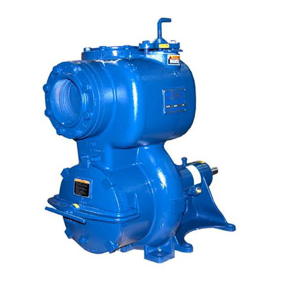
See Figure 1 for the approximate physical dimen configuration, and priming must be tailored to the sions of this pump. OUTLINE DRAWING Figure 1. Pump Model 16A20-B INSTALLATION PAGE B - 1... -
Page 9: Preinstallation Inspection
OM‐00710 10 SERIES PREINSTALLATION INSPECTION POSITIONING PUMP The pump assembly was inspected and tested be fore shipment from the factory. Before installation, inspect the pump for damage which may have oc curred during shipment. Check as follows: Death or serious personal injury and damage to the pump or components a. -
Page 10: Suction And Discharge Piping
10 SERIES OM‐00710 Installation closer to the pump may result in erratic SUCTION AND DISCHARGE PIPING readings. SUCTION LINES Pump performance is adversely effected by in creased suction lift, discharge elevation, and fric To avoid air pockets which could affect pump prim tion losses. -
Page 11: Suction Lines In Sumps
OM‐00710 10 SERIES Suction Lines In Sumps of one or both pumps. To avoid this, position the suction inlets so that they are separated by a dis If a single suction line is installed in a sump, it tance equal to at least 3 times the diameter of the should be positioned away from the wall of the suction pipe. -
Page 12: Discharge Lines
10 SERIES OM‐00710 DISCHARGE LINES NOTE The bypass line should be sized so that it does not affect pump discharge capacity; however, the by Siphoning pass line should be at least 1 inch (25,4 mm) in di ameter to minimize the chance of plugging. Do not terminate the discharge line at a level lower than that of the liquid being pumped unless a si... -
Page 13: Automatic Air Release Valve
OM‐00710 10 SERIES ter the pump completely cools, drain the liquid from the pump by removing the casing drain plug. Use caution when re moving the plug to prevent injury to per Except in certain specific applications (to sonnel from hot liquid. prevent flooding during service of an auto... -
Page 14: Alignment
10 SERIES OM‐00710 DISCHARGE PIPE CLEAN‐OUT COVER INSTALL AIR RELEASE VALVE IN HORIZONTAL POSITION DISCHARGE CHECK VALVE 90_ LONG RADIUS ELBOW SUPPORT PUMP DISCHARGE BRACKET SELF‐PRIMING CENTRIFUGAL PUMP BLEED LINE 1” (25,4 MM) DIA. MIN. (CUSTOMER FUR NISHED) DO NOT EX SUCTION TEND BELOW PUMP LINE... -
Page 15: Coupled Drives
OM‐00710 10 SERIES When checking alignment, disconnect the power source to ensure that the pump will remain inoperative. Adjusting the alignment in one direction Figure 4B. Alignment of V‐Belt Driven Pumps may alter the alignment in another direc tion. Check each procedure after altering Check parallel adjustment by laying a straightedge alignment. -
Page 16: V-Belt Tensioning
10 SERIES OM‐00710 excessive power loss and possible bearing failure. Belt Span Select pulleys that will match the proper speed ra tio; overspeeding the pump may damage both pump and power source. Deflection Do not operate the pump without the guard in place over the rotating parts. - Page 17 OM‐00710 10 SERIES Table 1. Sheave Diameter (Inches) Table 2. Sheave Diameter (Millimeters) Deflection Force (Lbs.) Deflection Force (KG.) Belt Deflection Force Belt Deflection Force Uncogged Cogged Uncogged Cogged Hy‐T Belts & Torque‐Flex Hy‐T Belts & Torque‐Flex Uncogged & Machined Uncogged &...
-
Page 18: Operation - Section C
OM‐00710 10 SERIES OPERATION - SECTION C Review all SAFETY information in Section A. Add liquid to the pump casing when: 1. The pump is being put into service for the Follow the instructions on all tags, labels and first time. decals attached to the pump. -
Page 19: Operation
OM‐00710 10 SERIES Consult the operating manual furnished with the Leakage pump power source before attempting to start the No leakage should be visible at pump mating sur power source. faces, or at pump connections or fittings. Keep all line connections and fittings tight to maintain maxi If an electric motor is used to drive the pump, re... -
Page 20: Stopping
OM‐00710 10 SERIES Block the suction line and start the pump. At oper normal for bearings, and they can operate safely to ating speed the pump should pull a vacuum of 20 at least 180_F (82_C). inches (508,0 mm) or more of mercury. If it does Checking bearing temperatures by hand is inaccu... - Page 21 10 SERIES OM‐00710 TROUBLESHOOTING - SECTION D Review all SAFETY information in Section A. Before attempting to open or service the pump: 1. Familiarize yourself with this manual. 2. Disconnect or lock out the power source to ensure that the pump will remain inoperative.
- Page 22 OM‐00710 10 SERIES TROUBLE POSSIBLE CAUSE PROBABLE REMEDY Impeller or other wearing parts worn Replace worn or damaged parts. PUMP STOPS OR FAILS TO DELIVER or damaged. Check that impeller is properly RATED FLOW OR centered and rotates freely. PRESSURE (cont.) Impeller clogged.
- Page 23 10 SERIES OM‐00710 equipped) between regularly scheduled inspec PREVENTIVE MAINTENANCE tions can indicate problems that can be corrected Since pump applications are seldom identical, and before system damage or catastrophic failure oc pump wear is directly affected by such things as curs.
- Page 24 PUMP MAINTENANCE AND REPAIR ‐ SECTION E MAINTENANCE AND REPAIR OF THE WEARING PARTS OF THE PUMP WILL MAINTAIN PEAK OPERATING PERFORMANCE. STANDARD PERFORMANCE FOR PUMP MODEL 16A20-B Based on 70_F (21_C) clear water at sea level Contact the Gorman‐Rupp Company to verify per...
- Page 25 OM‐00710 10 SERIES SECTION DRAWING PARTS PAGE Figure 1. Pump Model 16A20-B PAGE E - 2 MAINTENANCE & REPAIR...
- Page 26 10 SERIES OM‐00710 PARTS LIST Pump Model 16A20‐B (From S/N 818301 Up) If your pump serial number is followed by an “N”, your pump is NOT a standard production model. Contact the Gorman‐Rupp Company to verify part numbers. ITEM PART NAME PART MAT'L ITEM...
- Page 27 OM‐00710 10 SERIES PUMP AND SEAL DISASSEMBLY 4. Check the temperature before opening any covers, plates, or AND REASSEMBLY plugs. 5. Close the suction and discharge Review all SAFETY information in Section A. valves. 6. Vent the pump slowly and cau Follow the instructions on all tags, label and de...
- Page 28 10 SERIES OM‐00710 Back Cover Removal (when facing the drive end of the shaft) as shown in Figure 2. Use caution not to damage the shaft or keyway. When the impeller breaks loose, remove The wear plate (73) is easily accessible and may be the lathe dog and wood block.
- Page 29 OM‐00710 10 SERIES Shaft and Bearing Removal and Disassembly be replaced any time the shaft and bear ings are removed. When the pump is properly operated and main tained, the pedestal should not require disassem Clean the pedestal, shaft and all component parts bly.
- Page 30 10 SERIES OM‐00710 Shaft and Bearing Reassembly and movement has occurred, use a suitably sized Installation sleeve and a press to reposition the bearings against the shaft shoulders. Clean and inspect the bearings as indicated in If heating the bearings is not practical, use a suit Shaft and Bearing Removal and Disassembly.
- Page 31 OM‐00710 10 SERIES bearing retainer with the retaining ring (41). Check or emery cloth. If excessive wear exists, the shaft the shaft endplay. will have to be replaced. The seal is not normally reused because wear pat NOTE terns on the finished faces cannot be realigned Shaft endplay should be between .002 and .010 during reassembly.
- Page 32 10 SERIES OM‐00710 O‐RING ROTATING SEAL SEAL PLATE ELEMENT SPRING STATIONARY IMPELLER SEAL SEAT SHIMS SHAFT SLEEVE IMPELLER SHAFT IMPELLER OIL SEAL SPRING CENTERING WASHER BELLOWS STATIONARY DRIVE BAND ELEMENT Figure 3. Seal Assembly Press the stationary subassembly (consisting of the stationary seat, O‐rings and stationary ele...
- Page 33 OM‐00710 10 SERIES Impeller Installation and Adjustment Back Cover Installation If the wear plate (73) was removed for replace Inspect the impeller and replace it if cracked or ment, secure it to the cover plate (66) using the at badly worn. Install the same thickness of impeller taching hardware (63 and 64) at this time.
- Page 34 10 SERIES OM‐00710 valve gasket (85) and weights (84 and 86) using LUBRICATION hardware (82 and 83). Position the assembled check valve in the mounting slot in the seat. Bearings NOTE The pedestal was fully lubricated when shipped Apply `Permatex Aviation No. 3 Form‐A‐Gasket' or from the factory.
- Page 35 For U.S. and International Warranty Information, Please Visit www.grpumps.com/warranty or call: U.S.: 419-755-1280 International: +1-419-755-1352 For Canadian Warranty Information, Please Visit www.grcanada.com/warranty or call: 519-631-2870 GORMAN‐RUPP PUMPS...
Need help?
Do you have a question about the 16A20-B and is the answer not in the manual?
Questions and answers