
Related Manuals for FS S3270 Series


Summary of Contents for FS S3270 Series
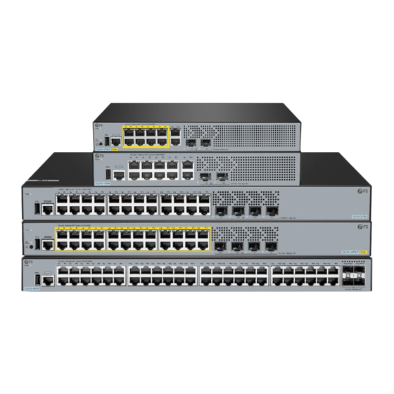
- Page 1 S3270 Series Switches Hardware Installation and Maintenance Guide V1.0.2307A Innovation · Expertise · Agility...
- Page 2 Safety Statement: • To avoid harm to people and equipment, please read the safety recommendations in the Safety Precautions for FS Switches before installing the FS Switch. Verify that the requirements described in the Safety Precautions for FS •...
-
Page 3: Table Of Contents
Contents 1. Hardware Installation and Parts Replacement 1.1 Installation Procedure 1.2 Installation Preparation 1.3 Installing a Switch 1.4 Connecting a Switch 1.5 Post-Installation Checks 1.6 System Commissioning 1.7 Parts Replacement 2. Troubleshooting After Installation 2.1 Troubleshooting Flowchart 2.2 Guide to Using Switches 2.3 Guide to Using Optical Modules Innovation ·... -
Page 4: Hardware Installation And Parts Replacement
Hardware Installation and Parts Replacement S3270 series switches are the new generation of Gigabit Ethernet switches, which are mainly used for campus access. With a brand-new hardware architecture and modular operating system, this series of products provide larger resource table entries, faster hardware processing performance, and higher operation and usage experience. -
Page 5: Installation Procedure
Hardware Installation and Parts Replacement Switch Hardware Installation and Maintenance Guide 1.1 Installation Procedure Installation Preparation Installing a Switch Installing Modules Connecting a Switch Post-Installation Checks System Commissioning 1.2 Installation Preparation Confirm the following before installation: The installation site provides sufficient space for heat dissipation. •... - Page 6 Hardware Installation and Parts Replacement Switch Hardware Installation and Maintenance Guide 1.2.2 Mounting the Cabinet or Rack When mounting the cabinet, please note the following: All expansion bolts for fastening the cabinet base to the ground should be installed and tightened in •...
-
Page 7: Installing A Switch
Multimeter, bit error rate tester (BERT), and optical power meter Meters • The S3270 series switch is delivered without a tool kit. You need to prepare a tool kit by yourself. 1.3 Installing a Switch Precautions : Please confirm the following before installing the switch: •... - Page 8 Ethernet cable only indoors. Take lightning protection measures if they need to be routed outdoors. 1.3.1 Mounting the Switch in a Cabinet or Rack The S3270 series switch meets the EIA standard size and can be installed in a 19-inch wiring closet with the following installation procedure:...
- Page 9 Hardware Installation and Parts Replacement Switch Hardware Installation and Maintenance Guide Figure 3: Cabinet lug installation 1.3.2 Mounting the Switch on a Workbench In most cases, users do not have a standard 19-inch rack. Therefore, the most common method is to place the switch on a clean workbench.
-
Page 10: Connecting A Switch
1.4.2 Connecting Power Cables There is one ground terminal on the back of the S3270 series switch chassis, which should be connected to the grounding lug of the rack first, and then connect the grounding lug to the grounding bar of the equipment room. - Page 11 Hardware Installation and Parts Replacement Switch Hardware Installation and Maintenance Guide Turn off the power module and the external power supply system for the switch. Connect the power cable to the power module. - Perform the following steps to connect the AC power cable: Insert the plug of the AC power cable into the power socket in the AC pwer module.
-
Page 12: Post-Installation Checks
Hardware Installation and Parts Replacement Switch Hardware Installation and Maintenance Guide 1.5 Post-Installation Checks 1.5.1 Verifying Cabinet External power supply matches the distribution panel of the cabinet. . The front and back doors can be closed after the switch is installed in the cabinet. . - Page 13 Hardware Installation and Parts Replacement Switch Hardware Installation and Maintenance Guide Step 1: Connecting the Ethernet Cable Plug the DB-9 connector of the Ethernet cable into the serial port of the PC. Connect RJ45 connector of the Ethernet cable to the console port of the switch. Step 2: Check the Serial Port Number Open Device Manager on the computer and check the serial port number.
- Page 14 Hardware Installation and Parts Replacement Switch Hardware Installation and Maintenance Guide Step 3: Start Terminal Emulation Software on the Computer (Such as PUTTY) Step 4: Setting Terminal Parameters Parameter requirements: Baud rate is 9600, connection type is Serial, fill in COM port number according to the actual situation. The specific diagram is as follows.
-
Page 15: Parts Replacement
Hardware Installation and Parts Replacement Switch Hardware Installation and Maintenance Guide Step 5: Once the serial port parameters are set, click <Open> to enter the CLI interface 1.6.2 Powering On the Switch Checklist before Power-On Check that the switch is fully grounded. Check that the power cord is properly connected. - Page 16 Hardware Installation and Parts Replacement Switch Hardware Installation and Maintenance Guide Ensure that the new optical module has the same center wavelength and complies with the same standards as the old one. . After removing the optical fibers from an optical module, cover the fiber connectors with dust caps. .
- Page 17 Hardware Installation and Parts Replacement Switch Hardware Installation and Maintenance Guide Figure 9: MPO Connector Pull out the optical module, plug the dustproof plug and dispose of it. - There are two types of buckles on the optical module. A pull-rod handle that needs to be turned over to open, as shown in Figure 10.
- Page 18 Hardware Installation and Parts Replacement Switch Hardware Installation and Maintenance Guide 5. Take out the new optical module from the package, and slowly insert it into the interface until you hear a "pop" sound, indicating that it has been installed in place. Find the fiber to be connected, find the interface corresponding to the fiber through the label on the fiber, remove the dust cap and connect the fiber to the interface.
-
Page 19: Troubleshooting After Installation
Troubleshooting After Installation Innovation · Expertise · Agility... -
Page 20: Troubleshooting Flowchart
Check the connector of power supply module each module Check the installation of Check the LEDs on the device other modules Check serial port connection Check the cable connection and parameters Contact FS Technical Support Innovation · Expertise · Agility... -
Page 21: Guide To Using Switches
Sometimes glitches can appear on these hardware. Contact Vendor Support: If there is still no output on the serial port, please contact FS technical support. Fault 4: The serial port console output is garbled Fault Symptom The serial port console output is garbled. -
Page 22: Guide To Using Optical Modules
Make sure that the character encoding used is consistent with the character encoding of the switch, usually ASCII encoding is used. Contact Vendor Support: If there is still no output on the serial port, please contact FS technical support. Fault 5: The link can not be set up between optical ports. - Page 23 Troubleshooting After Installation Switch Hardware Installation and Maintenance Guide If an optical module is not cleaned or protected properly, contaminants may accumulate on the fiber pin in the optical module. As a result, the coupling efficiency is reduced, optical signals are cut off, or even worse, the surface of the fiber pin is damaged permanently.
- Page 24 Troubleshooting After Installation Switch Hardware Installation and Maintenance Guide Figure 13: Cleaning Optical Fibers with Special Cleaning Tissues Place at least three cleaning tissues on the work bench. As shown in Figure 13, wipe the end of an optical connector from left to right or from right to left on a cleaning tissue, and then move the connector end to the unused part of the cleaning tissue to continue.
- Page 25 Troubleshooting After Installation Switch Hardware Installation and Maintenance Guide Figure 15: Using Fibers to Protect an Optical Module Cover unused optical connectors with protective caps, as shown in Figure 16, and then lay out fibers on the fiber rack or coil them in a fiber management tray to prevent fibers from being squeezed. Figure 16: Installing a Protective Cap on a Fiber If a receptacle or an optical connector has not been used for a long time and is not covered with a...
- Page 26 Troubleshooting After Installation Switch Hardware Installation and Maintenance Guide When cleaning a receptacle, insert the cotton swab and turn it slowly in the receptacle. Do not use too much strength because the receptacle may be damaged. If optical signals are lost during the operation of a device, use the preceding method to clean the receptacle or the optical connector.
- Page 27 FS has invested resources in product R&D, quality control, intelligent manufacturing, industry-leading experts, professional technical support,...
- Page 28 All is to provide customers with higher-performance, lower-power consumption, and the most cost-effective products, promoting clients' network upgrades. For more information and technical support, welcome to contact us at www.fs.com/contact_us Copyright © 2009-2023 FS.com Inc.All Rights Reserved.
Need help?
Do you have a question about the S3270 Series and is the answer not in the manual?
Questions and answers