Table of Contents
Advertisement
Quick Links
Advertisement
Table of Contents

Related Manuals for Standard Horizon DS35


Summary of Contents for Standard Horizon DS35
- Page 1 DS35 Digital Depth Sounder Owner’s Manual Marine Division of Vertex Standard...
-
Page 2: Limited Warranty
In the event of a defect, malfunction, or failure of the product to conform to specifications during the one- year warranty period, STANDARD HORIZON will repair or replace, at its option and without charge to the Purchaser, the product which upon examination by STANDARD HORIZON shall appear to be defective or not up to factory specifications. -
Page 3: Table Of Contents
5.2.2 Keel Offset ... 11 5.2.3 Display Damping ... 12 5.2.4 Transducer Setting ... 13 5.3 Simulation ... 13 6 Specifications ... 14 7 Maintenance ... 14 8 Troubleshooting ... 15 8.1 Technical Description ... 15 8.2 Troubleshooting ... 15 DS35 User Manual... -
Page 4: General Information
1 General Information Note: Please familiarize yourself with the entire manual and transducer installation guide before attempting installation. 1.1 Introduction The DS35 is a high-quality digital depth sounder. Features include: • Depth readings from 3 to 200 feet with the added capability of displaying depth in meters or fathoms. -
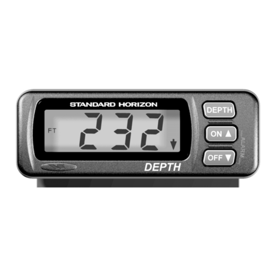
Page 5: Controls And Connectors
“LO” - off, “L1”, “L2”, or “L3” “+0.0” “d1”, “d2”, or “d3” DS35 User Manual key three seconds to change units “MTR”, “FT” and “FA”. key to turn on the alarm. key to turn off the alarm. keys and hold for three seconds to enable the alarm setting... -
Page 6: Figure 1. Transducer Types
0.19" 3.125" Figure 1. Transducer types 3.3 Replacement Parts The following parts may be ordered from the STANDARD HORIZON Parts Department. To order, call: 562-404-2700 Ext 351 Part ... Part Number Flush Mount Panel Gasket ... 108007023A Flush Mount Bracket Stud/Washer (2) ... 113001003A Flush Mount Bracket Stud/Washer Screw (2) ... -
Page 7: Figure 3. Rear Panel Flush Mount Installation
2. Fasten the instrument with either the gimbal Figure 3. Rear panel flush mount installation Pattern for cutting hole in dashboard " " DS35 User Manual Figure 2. Fuse Panel Connection Fuse Panel Ground mounting bracket or the flush mount mounting bracket and nuts provided. -
Page 8: Figure 4. Gimbal Mount Dimensions
" (106mm) Washers (2) Dashboard ( to 1 " (3 to 27mm)) " (65mm) 2" (51mm) Stud (2) Nut (2) Bracket Washers (2) Screws (2) Trunnion Screws (2) Mounting Bracket Mounting Surface Trunnion Screws (2) Mounting Bracket DS35 User Manual... -
Page 9: Operation
Press the to normal operation. Or to disable the shallow alarm, press the key until the display decreases to “OFF”. DS35 User Manual Press and hold for 3 seconds Display alternates between these two Press to set... -
Page 10: Setting Deep Alarm
Press to exit Depth Display Press to exit Depth Display key. The alarm Depth Alarm Icon key. The alarm No Depth Alarm Icon Increasing Trend Decreasing Trend DS35 User Manual... -
Page 11: Secondary Settings
Press One Press both to step to next level: Keel Offset DS35 User Manual 5.2.2 Keel Offset In the Secondary mode, with the Lamp Intensity level displayed, press the to the Keel Offset display; “+0.0” will be displayed for adjustment. Keel Offset can be adjusted for any of the following situations. -
Page 12: Display Damping
Press both Hold for 3 seconds Press Both Press Both Press One Press both to step to next level: Set Transducer or Press to exit DS35 User Manual... -
Page 13: Transducer Setting
5.2.4 Transducer Setting The Transducer Setting function enables the user to optimise the operation of the DS35 for the particular transducer installed. Transducer performance varies widely, larger diameter transducers produce strong signals resulting in improved deep water performance but can suffer from reduced shallow water performance, due to transducer ringing. -
Page 14: Specifications
• 50 watts RMS RF Interference • 6 dB maximum quieting on any marine radio channel with 3 dB gain antenna within 1 meter of the DS35 Standard Horizon Factory Repair Facility 115 North Wright Brothers Drive Salt Lake City, UT 84116... -
Page 15: Troubleshooting
Check the transducer cable for cuts and sharp bends. c Substitute the transducer with a known good Standard Horizon transducer, hold it over the side of the boat into the water to see if the instrument functions. This isolates cause of problem (transducer or instrument). - Page 16 Marine Division of Vertex Standard 17210 Edwards Road Cerritos, CA 90703 EED4100BD Telephone: 562/404-2700 STANDARD HORIZON ALL RIGHTS RESERVED PRINTED IN NEW ZEALAND 1951124A MN000130 April 2001...
Need help?
Do you have a question about the DS35 and is the answer not in the manual?
Questions and answers