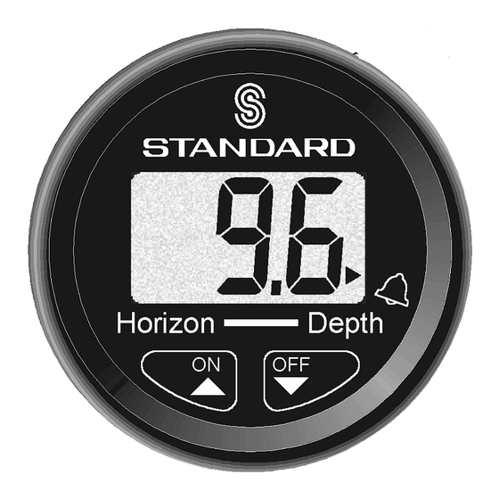
Summary of Contents for Standard Horizon DS41
- Page 1 Standard 2 Inch Installation Dual Station Operation NMEA Repeater Reads in Feet Fathoms or Meters Adjustable Prop or Surface Offset Shallow and Deep alarms DS41 Digital Depth Sounder Owner’s Manual...
-
Page 2: Table Of Contents
Transom Installation ... 13 In-Hull Installation ... 13 Appendix A – Dual Station Operation ... 14 Master/Slave Selection ... 14 Linked or Separate Selection ... 15 Appendix B – NMEA Repeater Mode ... 16 DS41 Owner’s Manual Contents DS41/HS/2G DS41 Owner’s Manual... -
Page 3: Specifications
• Display Updating 1 second. Display is backlit for Night Operation Alarm On/ Change Value Up DS41 Owner’s Manual • Operating Voltage 9.5 VDC to 16.5 VDC. • Operating Temperature 3-character LCD 0°C to 50°C (32°F to 122°F). • Current Drain 150mA max, including internal buzzer. -
Page 4: Operation
The alarm can also be disabled by pressing both the " and # keys for 5 seconds. The word !"" will be displayed but the alarm depth will be retained for Note: Press for 3 Seconds Note: future use. DS41 Owner’s Manual 3... -
Page 5: Deep Alarm
" and # keys for 5 seconds. The word !"" will be displayed but the alarm depth will be retained for future use. DS41 Owner’s Manual Instrument Setup Keel/Surface Offset An offset may be automatically added to or subtracted from the depth reading to compensate for the location of the transducer. -
Page 6: Transducer Setting
" and # keys simultaneously. Alternatively, if no keys are pressed for a period of 5 seconds normal depth display will resume. Press simultaneously The display will now indicate the current water depth in the selected display unit. DS41 Owner’s Manual 5 Meters... -
Page 7: Troubleshooting
1. Re-route power and transducer cables away from engine, ignition wires and battery cables. 2. Add feed-through filter capacitor on the positive terminal of the ignition coil. 3. Add an alternator whine filter to alternator. 4. Replace spark plug wire with resistive type. DS41 Owner’s Manual... -
Page 8: What Comes With Your Digital Depth Sounder
Mounting Bracket ... With mounting hardware Extension Power Cord ... 6 feet long with quick-disconnect connectors Twist Lock Face Plate ... Round Options DTS50 Plastic Low Profile Transducer DTS52 Bronze Long Stem Thru-hull Transducer DTS51 Transom Mount Transducer DS41 Owner’s Manual 7... -
Page 9: Replacement Parts
Square Face Plate ... Part Number 568001012A Round Face Plate ... Part Number 568002012A Gasket ... Part Number RRDS410001 Mounting Bracket ... Part Number 160001020A Mounting Nut ... Part Number 580010123A DS41 Owner’s Manual 2.75" 13° DTS55 In-Hull Transducer 2.125"... -
Page 10: Installation
Orient the bracket in such a manner that it does not cover the buzzer. 5. Tighten the mounting nut until the bracket is secure. 2.5" 2.5" INTERCHANGEABLE FACE PLATES SQUARE FACE PLATE .5" 3.75" Note: DS41 Owner’s Manual 9... - Page 11 Figure 2. Depth Sounder Installation FACE PLATE Figure 3. Side View of Mounted Depth Sounder DS41 Owner’s Manual 7. Obtain the power from a 12 V source as directly as possible. Avoid power circuits which share loads with ignition, alternators, radio transmitters, etc.
-
Page 12: Transducer Installation
Note: Transducer cable may be extended up to 15 additional feet but depth performance may be affected. Use 22 gauge, two-wire, shielded cable, using RCA/Phono connectors, or use EX375D 15 foot extension cable. DS41 Owner’s Manual... -
Page 13: Sailboats
Recommended Area FULL KEEL Figure 4. Sailboat Transducer Figure 6. Transom Mount Transducer Location DS41 Owner’s Manual transducer is not shaded by the prop shaft(s). On displacement hull powerboats (such as trawlers), the transducer should be mounted amidships, relatively close to the keel (centerline of the hull). -
Page 14: Transom Installation
6. To receive a proper echo from the bottom, the bottom of the PVC pipe may have to be cut at the deadrise angle of the hull. RUBBER GROMMET SEAL CAP PVC PIPE TRANSDUCER Figure 7. In-Hull Installation DS41 Owner’s Manual... -
Page 15: Appendix A - Dual Station Operation
Appendix A – Dual Station Operation Multiple DS41 instruments can be installed on a single vessel. These instruments can be connected together and configured to operate in a dual station configuration. One instrument is designated as a master and all other instruments, connected to it, are configured as slaves. -
Page 16: Linked Or Separate Selection
Linked or Separate Selection By default a dual station pair of DS41 instruments automatically keep the following settings the same in both instruments: Alarms On/Off Alarm Values (Deep and Shallow) Keel Offset (see note) Units of measure (see note) Example: Switching an alarm off on the slave instrument will also switch the alarm off on the master instrument. -
Page 17: Appendix B - Nmea Repeater Mode
Appendix B – NMEA Repeater Mode The DS41 can be configured to operate as a NMEA repeater. In this mode it will display depth information from any depth sounder outputing DPT or DBT NMEA depth data (no other NMEA depth sentences are supported).


Need help?
Do you have a question about the DS41 and is the answer not in the manual?
Questions and answers