Table of Contents
Troubleshooting

Related Manuals for Miller XMT 425 MPa Auto-Line CE


Summary of Contents for Miller XMT 425 MPa Auto-Line CE
- Page 1 OM-257343E 2016−06 Processes Multiprocess Welding Description Arc Welding Power Source ™ XMT 425 MPa Auto-Line File: MULTIPROCESS For product information, Owner’s Manual translations, and more, visit www.MillerWelds.com...
- Page 2 We know you don’t have time to do it any other way. That’s why when Niels Miller first started building arc welders in 1929, he made sure his products offered long-lasting value and superior quality.
-
Page 3: Table Of Contents
TABLE OF CONTENTS SECTION 1 − SAFETY PRECAUTIONS - READ BEFORE USING ....... . . 1-1. - Page 4 TABLE OF CONTENTS SECTION 8 − SMAW/CAC-A OPERATION ........... . . 8-1.
- Page 5 DECLARATION OF CONFORMITY for European Community (CE marked) products. ITW Welding Italy S.r.l Via Privata Iseo 6/E, 20098 San Giuliano M.se, (MI) Italy declares that the product(s) identified in this declaration conform to the essential requirements and provisions of the stated Council Directive(s) and Standard(s).
-
Page 7: Section 1 − Safety Precautions - Read Before Using
SECTION 1 − SAFETY PRECAUTIONS - READ BEFORE USING som 2015−09 Protect yourself and others from injury — read, follow, and save these important safety precautions and operating instructions. 1-1. Symbol Usage DANGER! − Indicates a hazardous situation which, if Indicates special instructions. - Page 8 D Remove stick electrode from holder or cut off welding wire at FUMES AND GASES can be hazardous. contact tip when not in use. D Wear body protection made from durable, flame−resistant material Welding produces fumes and gases. Breathing (leather, heavy cotton, wool). Body protection includes oil-free these fumes and gases can be hazardous to your clothing such as leather gloves, heavy shirt, cuffless trousers, high health.
-
Page 9: Additional Symbols For Installation, Operation, And Maintenance
1-3. Additional Symbols For Installation, Operation, And Maintenance FIRE OR EXPLOSION hazard. MOVING PARTS can injure. D Do not install or place unit on, over, or near D Keep away from moving parts such as fans. combustible surfaces. D Keep all doors, panels, covers, and guards D Do not install unit near flammables. -
Page 10: California Proposition 65 Warnings
1-4. California Proposition 65 Warnings Welding or cutting equipment produces fumes or gases This product contains chemicals, including lead, known to which contain chemicals known to the State of California to the state of California to cause cancer, birth defects, or other cause birth defects and, in some cases, cancer. -
Page 11: Section 2 − Definitions
SECTION 2 − DEFINITIONS 2-1. Additional Safety Symbols And Definitions Warning! Watch Out! There are possible hazards as shown by the symbols. Safe1 2012−05 Wear dry insulating gloves. Do not touch electrode with bare hand. Do not wear wet or damaged gloves. Safe2 2012−05 Protect yourself from electric shock by insulating yourself from work and ground. - Page 12 When power is applied failed parts can explode or cause other parts to explode. Safe26 2012−05 Always wear long sleeves and button your collar when servicing unit. Safe28 2012−05 After taking proper precautions as shown, connect power to unit. Safe29 2012−05 Do not use one handle to lift or support unit.
-
Page 13: Miscellaneous Symbols And Definitions
2-2. Miscellaneous Symbols And Definitions Amperage Foot Control Voltage Sensing Feeder Alternating Current (AC) Gas Metal Arc Output Welding (GMAW) Voltage Conventional Load Voltage Direct Current Voltage Input (DC) Panel Constant Current Protective Earth (Ground) Increase Arc Force Line Connection Circuit Breaker Three Phase Rated No Load... -
Page 14: Section 3 − Specifications
SECTION 3 − SPECIFICATIONS 3-1. Features And Benefits Auto-Linet Power Management Technology is circuitry that automatically adapts the power source to the primary voltage being applied (see Section 4-7). LVCt Line Voltage Compensation is circuitry that keeps the power source output constant regardless of input pow- er fluctuation. -
Page 15: Dimensions And Weight
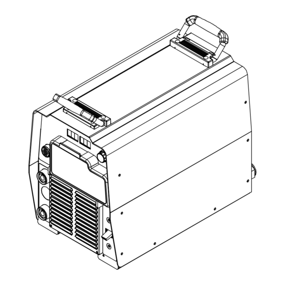
3-5. Dimensions And Weight Hole Layout Dimensions 11-3/4 in. (298 mm) 24 in. (610 mm) 1-11/16 in. (42 mm) 17 in. 15-3/4 in. (400 mm) (432 mm) 19-3/32 in. (485 mm) 8-11/16 in. (221 mm) 1-17/32 in. (39 mm) 1/4-20 UNC -2B thread 12-1/2 in. -
Page 16: Duty Cycle And Overheating
3-7. Duty Cycle And Overheating Duty Cycle is percentage of 10 min- utes that unit can weld at rated load without overheating. If unit overheats, output stops, a Help message is displayed and cooling fan runs. Wait fifteen min- utes for unit to cool. Reduce amper- age or voltage, or duty cycle before welding. -
Page 17: Section 4 − Installation
SECTION 4 − INSTALLATION 4-1. Selecting A Location Movement Do not move or operate unit where it could tip. Location And Airflow Special installation may be required where gasoline or volatile liquids are present − see NEC Article 511 or CEC Section 20. -
Page 18: Selecting Cable Sizes
4-2. Selecting Cable Sizes* NOTICE − The Total Cable Length in Weld Circuit (see table below) is the combined length of both weld cables. For example, if the power source is 30 m (100 ft) from the workpiece, the total cable length in the weld circuit is 60 m (2 cables x 30 m). Use the 60 m (200 ft) column to determine cable size. -
Page 19: Remote 14 Receptacle Information
4-4. Remote 14 Receptacle Information Socket* Socket Information 24 volts AC. Protected by supplementary protect- or CB2. 24 VOLTS AC Contact closure to A completes 24 volts AC contactor control circuit. C L N Output to remote control; 0 to +10 volts DC, +10 volts DC in MIG mode. -
Page 20: Optional Gas Valve Operation And Shielding Gas Connection
4-6. Optional Gas Valve Operation And Shielding Gas Connection Obtain gas cylinder and chain to running gear, wall, or other station- ary support so cylinder cannot fall and break off valve. Cylinder Regulator/Flowmeter Install so face is vertical. Gas Hose Connection GAS IN Fitting has 5/8-18... -
Page 21: Electrical Service Guide
4-7. Electrical Service Guide Elec Serv 2014−01 NOTICE − INCORRECT INPUT POWER can damage this welding power source. Phase to ground voltage shall not exceed +10% of rated input voltage. NOTICE − Actual input voltage should not be 10% less than minimum and/or 10% more than maximum input voltages listed in table. If actual input voltage is outside this range, output may not be be available. -
Page 22: Connecting 3-Phase Input Power
4-8. Connecting 3-Phase Input Power = GND/PE Earth Ground Tools Needed: input2 2012−05 − Ref. 803 766-C /Ref. 804 531 OM-257343 Page 16... - Page 23 4-8. Connecting 3-Phase Input Power (Continued) voltage available at site. This unit can be con- Input Conductors (L1, L2 And L3) Installation must meet all National and nected to any input power between 208 and Local Codes − have only qualified per- Disconnect Device Line Terminals 575 VAC without removing cover to relink the sons make this installation.
-
Page 24: Section 5 − General Operation
SECTION 5 − GENERAL OPERATION 5-1. Front Panel Ref. 804 772-A / 316.029.725-A 12 Remote PC Interface Weld process operation sections de- The meters display the actual weld output 13 Setup Button scribe functionality of the identified items. values after arc initiation and remains dis- played for approximately three seconds 14 Gas Type Indicator Remote 14 Receptacle... -
Page 25: Mode Switch Settings
5-2. Mode Switch Settings Switch Position Process Output Control Panel Adjust Remote Adjust Scratch Start TIG GTAW Electrode Hot Amps % Panel Amps* Lift-Arc TIG GTAW Electrode Hot Amps % Panel Amps* GTAW Remote 14 Amps % Panel Amps GMAW Remote 14 Volts Volts... -
Page 26: Configuration Option Menu
5-3. Configuration Option Menu 316.029.725-A Mode Switch Setup Right Displays. SET−UP will be displayed momentarily. Remote 14 Receptacle The Configuration Option Menu provides a Configuration options are displayed in the Left Left Display means to customize some machine features Display. Settings are displayed in the Right Right Display for desired operation. - Page 27 Configuration Option Menu (Continued) V-Sense Feeder Weld Process V.SEN This option enables MIG (V.SEN MIG) or Pulsed MIG (V.SEN PULS) when the Mode Switch is in the VSENSE FEEDER position. See Section 7-2 for MIG operation or Section 7-4 for Pulsed MIG operation. Pulsed MIG Manual/Auto Control AUTO PULS...
-
Page 28: Section 6 − Gtaw Operation
Configuration Option Menu (Continued) Revision Information INFO This option identifies the unit’s weld library (INFO LIB) and firmware revision (INFO REV). Press the Setup Button while the unit is display- ing INFO LIB to identify the unit’s weld library. Press the Setup Button while the unit is display- ing INFO REV to identify the unit’s firmware revi- sion. -
Page 29: Scratch Start Tig Welding Mode - Gtaw Process
6-2. Scratch Start TIG Welding Mode - GTAW Process 7 2. 0 316.029.725-A Setup Operation Weld terminals are energized at all times in Scratch Start TIG welding The Adjust Control is used to set desired For typical system connections refer to mode. -
Page 30: Lift-Arc Tig Welding Mode - Gtaw Process
6-3. Lift-Arc TIG Welding Mode - GTAW Process 1 3. 5 316.029.725-A 1 − 2 “Touch” Seconds Do NOT Strike Like A Match! Rotate Mode Switch to LIFT-ARC TIG posi- welding, momentarily depress output Weld terminals are energized at all tion as shown. -
Page 31: Tig Welding Mode - Gtaw Process
6-4. TIG Welding Mode - GTAW Process 316.029.725-A Setup Operation Weld terminals energized through the remote control in TIG For typical system connections refer to The Adjust Control is used to set desired welding mode. Section 6-1. preset amperage. Rotate Mode Switch to TIG position as A remote control is required to turn on the Mode Switch shown. -
Page 32: Section 7 − Gmaw/Gmaw-P/Fcaw Operation
SECTION 7 − GMAW/GMAW-P/FCAW OPERATION 7-1. Typical Connection For Remote Control Feeder GMAW/GMAW-P/FCAW Process 804 938-A Workpiece Use of shielding gas is dependant on Wire Turn off power before making Type. connections. Remote 14-Receptacle The connection diagram illustrates Wire Feeder DCEP (reverse polarity) suitable for all Positive (+) Weld Output Terminal wires except self-shielded FCAW. -
Page 33: Mig Welding Mode - Gmaw/Fcaw Process
7-2. MIG Welding Mode - GMAW/FCAW Process 25.0 316.029.725-A Press the Setup Button to confirm the Weld terminals energized The preset voltage can be adjusted re- selection. The unit will acknowledge a through the remote control in MIG motely at the wire feeder if the feeder change of wire and gas information by dis- welding mode. -
Page 34: Mig - Wire And Gas Selection Table
7-3. MIG - Wire and Gas Selection Table WIRE TYPES** GAS TYPES DEFAULT INDUCTANCE .035 (0.9) STL ARGN CO2 (ARGON / CARBON DIOXIDE) .045 (1.2) STL ARGN OXY (ARGON / OXYGEN) .052 (1.4) STL Steel .035 (0.9) STL CO2 (CARBON DIOXIDE) .045 (1.2) STL .035 (0.9) FCAW ARGN CO2 (ARGON / CARBON DIOXIDE) *... -
Page 35: Pulsed Mig Welding Mode - Gmaw-P Process
7-4. Pulsed MIG Welding Mode - GMAW-P Process 25.0 316.029.725-A Pulsed MIG − Wire and Gas Selection Arc Length - Pulsed MIG Manual Control Weld terminals energized Table for available wires and gases (see Section 5-3) through the remote control in (see Section 7-5). -
Page 36: Pulsed Mig - Wire And Gas Selection Table
7-5. Pulsed MIG - Wire and Gas Selection Table WIRE TYPES* GAS TYPES .035 (0.9) STL ARGN CO2 (ARGON / CARBON DIOXIDE) Steel .045 (1.2) STL ARGN OXY (ARGON / OXYGEN) .045 (1.2) MCOR Metal Core ARGN CO2 (ARGON / CARBON DIOXIDE) .052 (1.4) MCOR TRI MIX (TRI-GAS MIXTURE) .035 (0.9) SSTL... -
Page 37: Remote Process Select
7-6. Remote Process Select This power source can be used with wire feeders that support Remote Process Se- lect. This feature allows the operator to switch the active welding process between MIG and Pulsed MIG at the wire feeder. To determine if the welding system is Remote Process Select capable, connect the wire feeder to the power source and review the... -
Page 38: Typical Connection For Voltage-Sensing Feeder Gmaw/Gmaw-P/Fcaw Process
7-7. Typical Connection For Voltage-Sensing Feeder GMAW/GMAW-P/FCAW Process Turn off power before mak- ing connections. Positive (+) Weld Output Terminal Negative (−) Weld Output Terminal Ground Cable to Workpiece Workpiece Voltage Sensing Clamp Gun Trigger Receptacle Wire Feeder Gas Hose 10 Gas Cylinder Use of shielding gas is dependant on Wire Type. -
Page 39: V-Sense Feeder Welding Mode - Gmaw/Fcaw Process
7-8. V-Sense Feeder Welding Mode - GMAW/FCAW Process 25.0 316.029.725-A Operation Rotate Adjust Control to select desired gas. Weld terminals are energized at all times in V-Sense Feeder welding While the Volts Indicator is lit under the Left Press the Setup Button again to confirm the mode. -
Page 40: V-Sense Feeder Welding Mode - Gmaw-P Process
7-9. V-Sense Feeder Welding Mode - GMAW-P Process 25.0 R200 316.029.725-A ment of Arc Control, Wire Type, Gas Type Higher settings narrow the arc cone, re- Weld terminals are energized at all and Arc Length. duces puddle fluidity and crowns the weld times in V-Sense Feeder welding bead appearance. -
Page 41: Section 8 − Smaw/Cac-A Operation
SECTION 8 − SMAW/CAC-A OPERATION 8-1. Typical Connection For SMAW And CAC-A Process Turn off power before mak- ing connections. Electrode Holder (Carbon Arc) For CAC-A process connect car- bon arc cutting torch to to positive weld output terminal. Electrode Holder Positive (+) Weld Output Terminal Remote 14 Receptacle... -
Page 42: Stick Remote Welding Mode - Smaw/Cac-A Process
8-2. Stick Remote Welding Mode - SMAW/CAC-A Process 316.029.725-A Press the Setup Button repeatedly until the Weld terminals energized If the remote control has an amperage Arc Control light goes out to return to ad- through the remote control in Stick adjustment, the adjustment will func- justment of preset amperage. -
Page 43: Stick Hot Welding Mode - Smaw/Cac-A Process
8-3. Stick Hot Welding Mode - SMAW/CAC-A Process 7 2. 0 316.029.725-A Right Display, the Adjust Control is used to Programmable Hot Start Weld terminals are energized at all set desired preset amperage. times in Stick Hot welding mode. Press the Setup button repeatedly until Pressing the Setup Button allows adjust- Mode Switch HOT.S appears on the left display. -
Page 44: Section 9 − Maintenance & Troubleshooting
SECTION 9 − MAINTENANCE & TROUBLESHOOTING 9-1. Routine Maintenance Disconnect power Maintain more often before maintaining. during severe conditions. 3 Months Repair Or Replace Replace Cracked Replace Damaged Or Torch Body Cracked Unreadable Cables Labels Repair Or Replace Cracked Cables And Cords Clean Tighten Weld... -
Page 45: Help Displays
9-3. Help Displays All directions are in reference to the front of the unit. All circuitry referred to is lo- cated inside the unit. Help 1 Display HELP Indicates a malfunction in the primary power circuit. If this display is shown, contact a Fac- tory Authorized Service Agent. -
Page 46: Troubleshooting
9-4. Troubleshooting Trouble Remedy No weld output; unit completely inop- Place line disconnect switch in On position (see Section4-8 ). erative. Check and replace line fuse(s), if necessary, or reset circuit breaker (see Section 4-8). Check for proper input power connections (see Section4-8 ). No weld output;... - Page 47 Notes OM-257343 Page 41...
-
Page 48: Section 10 − Electrical Diagram
SECTION 10 − ELECTRICAL DIAGRAM Figure 10-1. Circuit Diagram OM-257343 Page 42... - Page 49 252 423-C OM-257343 Page 43...
-
Page 50: Section −11 − Parts List
SECTION −11 − PARTS LIST Ref. 244 004-B Figure 11-1. Parts Assembly OM-257343 Page 44... - Page 51 Item Dia. Part Mkgs. Description Quantity Figure 11-1. Parts Assembly ....216034 Wrapper W/Insulators ......... . .
- Page 52 Item Dia. Part Mkgs. Description Quantity Figure 11-1. Parts Assembly (Continued) ... . . 604176 Rcpt, Str Dx Grd 2P3W 15A 125V *5−15R ......
- Page 53 Item Dia. Part Mkgs. Description Quantity Figure 11-1. Parts Assembly (Continued) ♦218183 ....Rcpt Assy, Tw Lk Insul Fem (Tweco Type) (Fac-op) (Includes) ..
- Page 55 Effective January 1, 2016 (Equipment with a serial number preface of MG or newer) This limited warranty supersedes all previous Miller warranties and is exclusive with no other guarantees or warranties expressed or implied. LIMITED WARRANTY − Subject to the terms and conditions 90 Days —...
- Page 56 File a claim for loss or damage during Phone: 39 (0) 2982901 Fax: 39 (0) 298290-203 shipment. email: miller@itw−welding.it For assistance in filing or settling claims, contact your distributor and/or equipment manufacturer’s Transportation Department. © ORIGINAL INSTRUCTIONS − PRINTED IN USA 2016 Miller Electric Mfg. Co. 2016−01...
Need help?
Do you have a question about the XMT 425 MPa Auto-Line CE and is the answer not in the manual?
Questions and answers