Table of Contents
Advertisement
Quick Links
Specifications
lGeneral
Power Source:
Power consumption:
Dimensions (W×H×D):
Mass:
lAmplifier section
RMS Output Power: Dolby Digital Mode
lTotal RMS Dolby Digital
mode Power:
At 1kHz and total harmonic of 10%
lFront:
lCenter:
lSurround:
At 100Hz and total harmonic of 10%
lActive subwoofers:
DIN Output Power: Dolby Digital Mode:
lTotal DIN Dolby Digital mode Power:
At 1Hz and total harmonic of 1%
lFront:
lCenter:
AC 230V, 50Hz
25 W
430×68×423 mm
4 kg
1000 W
170 W/ Channel (6Ω)
260 W/ Channel (4Ω)
70 W/ Channel (4Ω)
260 W/ Channel (4Ω)
750 W
140 W/ Channel (6Ω)
180 W/ Channel (4Ω)
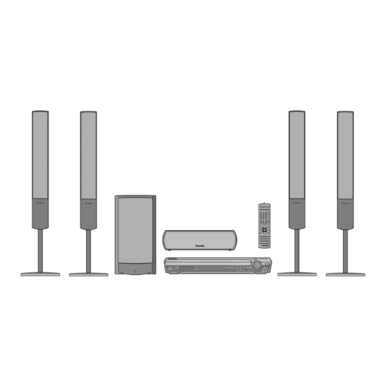
DVD Home Theater Sound System
SA-HT935EE
Colour
(S).......................Silver Type
lSurround:
At 100Hz and total harmonic of 1%
lSubwoofer:
lFM tuner section
Frequency Range:
Sensitivity:
S/N 26dB
Antenna Terminal:
lAM tuner section
Frequency Range:
AM Sensitivity S/N 20dB at
999kHz:
lPhone Jack:
Terminal:
lDisc section
Discs played [8 cm or 12 cm]:
(1) DVD-RAM (DVD-VR compatible, JPEG formatted discs)
(2) DVD-Audio
(3) DVD-Video
(4) DVD-R, DVD-RW (DVD-Video compatible)
+R, +RW (Video compatible)
© 2005 Panasonic AVC Networks Singapore Pte.
Ltd. All rights reserved. Unauthorized copying and
distribution is a violation of law.
ORDER NO.MD0503079C3
55 W/ Channel (4Ω)
180 W/ Channel (4Ω)
87.5-108.0MHz
(50kHz in step)
2.5µV (IHF)
2.2µV
75Ω (non balance)
522-1629kHz (9kHz in step)
560µV/m
Stereo 3.5 mm jack
Advertisement
Table of Contents

Subscribe to Our Youtube Channel
Related Manuals for Panasonic SA-HT935EE


Summary of Contents for Panasonic SA-HT935EE
- Page 1 (3) DVD-Video lFront: 140 W/ Channel (6Ω) (4) DVD-R, DVD-RW (DVD-Video compatible) lCenter: 180 W/ Channel (4Ω) +R, +RW (Video compatible) © 2005 Panasonic AVC Networks Singapore Pte. Ltd. All rights reserved. Unauthorized copying and distribution is a violation of law.
- Page 2 SA-HT935EE (5) CD-Audio (CD-DA) CD-Audio: 93 dB (6) Video CD Total harmonic distortion: (7) SVCD (Conforming to IEC62107) CD-Audio: 0.005 % (8) CD-R/CD-RW (CD-DA, Video-CD, SVCD, MP3, WMA, JPEG lVideo section formatted discs) Video system: (9) MP3/WMA Signal system: PAL 625/50, PAL 525/60,...
-
Page 3: Table Of Contents
SA-HT935EE CONTENTS Page Page 1 Use of Active Subwoofer 11.9. Removal of the Rotary Tray 1.1. Checking Player when Active Subwoofer is not used 11.10. Removal of the Open Lock Gear 2 Safety Precautions 11.11. Removal of the Close Lock Gear 2.1. - Page 4 SA-HT935EE 16 Adjustment Procedure 21 Block Diagram 16.1. Service Tools and Equipment 22 Schematic Diagram 16.2. Important points in adjustment 23 Printed Circuit Board Diagram 16.3. Storing and handling of test discs 24 Wiring Connection Diagram 16.4. Optical adjustment 25 Illustration of IC 痴, Transistors and Diodes...
-
Page 5: Use Of Active Subwoofer
SA-HT935EE 1 Use of Active Subwoofer 1.1. Checking Player when Active Subwoofer is not used 1. This unit uses the active subwoofer to supply the power of the component, and the active subwoofer should be connected to the component to check operational conditions of the component. -
Page 6: Safety Precautions
SA-HT935EE 2 Safety Precautions 2.1. GENERAL GUIDELINES 1. When servicing, observe the original lead dress. If a short circuit is found, replace all parts which have been overheated or damaged by the short circuit. 2. After servicing, see to it that all the protective devices such as insulation barriers, insulation papers shields are properly installed. -
Page 7: Before Repair And Adjustment (Using Active Subwoofer)
SA-HT935EE Caution Be sure no power is applied to the chassis or circuit, and observe all other safety precautions. 8. Minimize bodily motions when handling unpackaged replacement ES devices. (Otherwise harmless motion such as the brushing together of your clothes fabric or the lifting of your foot from a carpeted floor can generate static electricity (ESD) sufficient to damage an ES device). -
Page 8: Precaution Of Laser Diode
SA-HT935EE 6 Precaution of Laser Diode CAUTION : This product utilizes a laser. Invisible laser radiation is emitted from the optical pick up lens when the unit is turned on. Wavelength : 662nm(DVD)/785nm(VCD/CD) Maximum output radiation power from pick up : 100µW/VDE Laser radiation from pick up unit is safety level, but be sure the followings: 1. -
Page 9: General Description
SA-HT935EE 8 General Description 8.1. Operating instructions TUNING H.BASS H.BASS INDICATOR OPEN/CLOSE Standby/on indicator PROGRESSIVE DISC EXCHANGE CD MODE DISC SKIP INPUT SELECTOR Remote control signal sensor Direct select button/indicators TUNE MODE FM MODE PHONES Standby/on switch VOLUME MEMORY SYSTEM... -
Page 10: Disc Information
SA-HT935EE 8.2. Disc information Discs that can be played Indication in Disc Logo Remarks these operating instructions Recorded with devices using Version 1.1 of the Video Recording Format (a unified video recording standard), such as DVD video recorders, DVD video cameras, personal computers, etc. -
Page 11: About Highmat
SA-HT935EE 8.3. About HighMAT 8.3.1. What’s HighMAT? Consumers worldwide are using PCs to create their own collections of music, photos and even video by burning them onto CDs. But how these collections can be experienced across different devices can be confusing to navigate, time consuming to access for a DVD player, and be incomplete in terms of music information available to the customer. - Page 12 SA-HT935EE 8.3.2. Why take advantage of HighMAT? A Problem Defined:Today, when consumers create their own digital audio, video or photo collections on CD-R or other physical formats, there are numerous, inconsistent ways that devices read the data. For the consumer, the playback experience can be...
- Page 13 SA-HT935EE Conventional HighMAT Even though DVD player is CD-R/RW compatible, the inconsistent ways HighMAT compatible products play content back with consistent that various DVD players can read the music or photos files often leads interface. This includes products which are JPEG compatible products to a confusing and inconsistant playback experince.
- Page 14 SA-HT935EE HighMAT is now available for CD Burning and in Leading DVD Players HighMAT is a new technology that is now available in leading software and consumer electronic devices to dramatically improve the digital media experience when you create homemade CDs HighMAT delivers a simple, standardized way for PC software and consumer electronics devices to talk to each other and work better together.
- Page 15 SA-HT935EE When you create your homemade CDs with software that supports HighMAT CD burning, and then play them back on a DVD player that supports HighMAT, you get better, easier navigation. You get folders you can access with a single click of your DVD player´s remote control.
-
Page 16: Accessories
SA-HT935EE 9 Accessories AC cord Remote control System cable AM loop antenna Speaker cable FM indoor antenna Video Cable Speaker label... -
Page 17: Handling Precautions For Optical Pickup Unit
SA-HT935EE 10 Handling Precautions for Optical Pickup Unit The laser diode in the optical pickup unit may break down due to static electricity of clothes or human body. Special care must be taken avoid caution to electrostatic breakdown when servicing and handling the laser diode. - Page 18 SA-HT935EE...
-
Page 19: Disassembly And Main Component Replacement Procedures
SA-HT935EE 11 Disassembly and Main Component Replacement Procedures “ATTENTION SERVICER” Some chassis components may have sharp edges. Be careful when disassembling and servicing. 1. This section describes procedures for checking the operation of the major printed circuit boards and replacing the main components. -
Page 20: Disassembly Procedure
SA-HT935EE 11.1. Disassembly Procedure 11.2. Main Components and P.C.B. Locations... -
Page 21: Disassembling The Top Cabinet
SA-HT935EE 11.3. Disassembling the Top Cabinet Step 1 Remove 7 screws. Step 2 Remove the top cabinet in the direction of arrow. 11.4. Disassembling the Front Panel · Follow the (Step 1) - (Step 2) of Item 11.3. Step 6 Remove the front panel in the direction of arrow. -
Page 22: Disassembling The Tray Assembly
SA-HT935EE 11.5. Disassembling the Tray 11.7. Disassembling the Main P.C.B Assembly · Follow Item 11.4. Step 1 Unlock the claw and remove 9 screws. · Follow the (Step 1) - (Step 2) of Item 11.3. Step 2 Remove the main P.C.B. -
Page 23: Removal Of The Tray Base Guide (L) And Tray Base Guide
SA-HT935EE 11.8. Removal of the Tray Base Guide (L) and Tray Base Guide · Follow the (Step 1) - (Step 2) of Item 11.3. · Follow the (Step 1) - (Step 6) of Item 11.4. · Follow the (Step 1) - (Step 2) of Item 11.5. -
Page 24: Removal Of The Traverse Unit
SA-HT935EE Step 3 Rotate close lock gear to direction of arrow, press claw (b) and pull out close lock gear. 11.12. Removal of the Tray Motor Step 2 Flip the base mecha unit in vertical position. P.C.B. and Sensor P.C.B. -
Page 25: Removal Of The Loading Motor P.c.b
SA-HT935EE · Follow the (Step 1) - (Step 3) of Item 11.6. Step 1 Release the claw in the direction of arrow (1), and then push drive gear shaft up. Step 3 Release the 2 claws in the direction of arrow (1), and Step 2 Remove Drive Gear (A) and Drive Gear (B). -
Page 26: Removal Of The Cam Gear & Support Piece
SA-HT935EE 11.18. Removal of the Cam Gear & Support Piece · Follow the (Step 1) - (Step 2) of Item 11.3. · Follow the (Step 1) - (Step 6) of Item 11.4. · Follow the (Step 1) - (Step 2) of Item 11.5. -
Page 27: Assembly Of Tray Base
SA-HT935EE 11.20. Assembly of Tray Base · Follow the (Step 1) - (Step 2) of Item 11.3. · Follow the (Step 1) - (Step 6) of Item 11.4. · Follow the (Step 1) - (Step 2) of Item 11.5. Step 1 Rotate cam gear anti-clockwise. Align at position (C) as marking on gear with arrow. -
Page 28: Service Position
SA-HT935EE 12 Service Position Prepare service tools before proccess service position. Service Tools Loading Motor P.C.B - Main REEX0465 (11 pin) P.C.B 12.1. Checking & Repair Tray Motor P.C.B and Sensor P.C.B · Follow the (Step 1) - (Step 2) of Item 11.3. -
Page 29: Optical Pick-Up Self-Diagnosis And Replacement Procedure
SA-HT935EE 13 Optical Pick-up Self-Diagnosis and Replacement Procedure 13.1. Optical Pickup Breakdown Diagnosis The optical pickup self-diagnosis function and tilt adjustment check function have been included in this unit. When repairing, use the following procedure for effective Self-diagnosis and tilt adjustment.Be sure to use the self-diagnosis function before replacing the optical pickup when "NO DISC"... -
Page 30: Service Mode Table
SA-HT935EE 13.2. Service Mode Table 1 The service modes can be activated by pressing various button combination on the player and remote control unit. Player buttons Remote control unit buttons Application Note STOP Error code display (Refer to the item, “13.3. - Page 31 SA-HT935EE Error Code Error Content Additional error explanation F890 Sending message when message is Sending message to AV task being sent to AV task F891 Message couldn’t be sent to AV task Begin sending message to AV task F893 FROM falsification...
-
Page 32: Service Mode Table
SA-HT935EE 13.4. Service mode table 2 Pressing various button combinations on the player and remote control unit can activate the service modes. - Page 33 SA-HT935EE...
-
Page 34: Sales Demonstration Lock Function
SA-HT935EE 13.5. Sales demonstration lock function This function prevents discs from being lost when the unit is used for sales demonstrations by disabling the disc eject function. "LOCKED" is displayed on the unit, and ordinary operation is disabled. 13.5.1. Setting ·... -
Page 35: Self-Diagnosis Function
SA-HT935EE 14 Self-Diagnosis Function 14.2. Memorized Error Codes 14.2.1. Activating Self-Diagnosis Function 14.1. Automatic Displayed Error and Displaying Method Codes 1. Turn on the power. 14.1.1. Automatic Display Function 2. Select DVD/CD function. With no DVD/CD inserted in the player, press and hold down the F_SKIP button For a power unit error, the code is automatically displayed. -
Page 36: Service Precautions
SA-HT935EE 15 Service Precautions 15.1. Recovery after the DVD player is repaired · When FLASH ROM IC or DVD module P.C.B. is replaced, carry out the recovery processing to optimize the drive. Playback the recovery disk to process the recovery automatically. -
Page 37: Adjustment Procedure
SA-HT935EE 16 Adjustment Procedure 16.1. Service Tools and Equipment Application Name Number Tilt adjustment DVD test disc DVDT-S20 [SPG] TORX screw driver (T6) Available on sales route. (T6) or RFKZ0185 [SPG] Others Grease RFKXPG641 [SPG] Confirmation CD test disc PVCD-K06 or any other commercially... -
Page 38: Optical Adjustment
SA-HT935EE 16.4. Optical adjustment 16.4.1. Optical pickup tilt adjustment Measurement point Adjustment point Mode Disc Tangential adjustment screw T01 (inner periphery) play DVDT-S20 [SPG] Tilt adjustment screw T30 (center periphery) T43 (outer periphery) play Measuring equipment Adjustment value None (Main unit display for servicing is used.) Adjust to the minimum jitter value. -
Page 39: Abbreviations
SA-HT935EE 17 Abbreviations INITIAL/LOGO ABBREVIATIONS INITIAL/LOGO ABBREVIATIONS A0~UP ADDRESS ERROR TORQUE CONTROL ACLK AUDIO CLOCK ERROR TORQUE CONTROL AD0~UP ADDRESS BUS REFERENCE ADATA AUDIO PES PACKET DATA ENCSEL ENCODER SELECT ADDRESS LATCH ENABLE ETMCLK EXTERNAL M CLOCK (81MHz/40.5MHz) AMUTE AUDIO MUTE... - Page 40 SA-HT935EE INITIAL/LOGO ABBREVIATIONS INITIAL/LOGO ABBREVIATIONS READ ENABLE VBLANK V BLANKING RFENV RF ENVELOPE COLLECTOR POWER SUPPLY RF PHASE DIFFERENCE OUTPUT VOLTAGE (CD-ROM) REGISTER SELECT VCDCONT VIDEO CD CONTROL (TRACKING RSEL RF POLARITY SELECT BALANCE) RESET DRAIN POWER SUPPLY VOLTAGE RESERVE...
-
Page 41: Voltage Chart
SA-HT935EE 18 Voltage Chart 18.1. DVD Module P.C.B. IC8001 Re f No. MODE CD P LAY IC8001 Re f No. MODE CD P LAY Re f No. IC8001 MODE CD P LAY IC8001 Re f No. MODE CD P LAY IC8001 Re f No. -
Page 42: Main P.c.b
SA-HT935EE 18.2. Main P.C.B. IC2006 Re f No. MODE CD P LAY S TANDBY IC2007 Re f No. MODE CD P LAY S TANDBY IC2008 IC2009 Re f No. MODE CD P LAY S TANDBY IC2010 Re f No. MODE CD P LAY -6.7... -
Page 43: Fl P.c.b
SA-HT935EE Q2000 Q2001 Q2002 Q2003 Q2004 Re f No. MODE CD P LAY S TANDBY Re f No. Q2005 Q2006 Q2007 Q2026 MODE CD P LAY -4.5 S TANDBY Q2028 Q2029 Q2031 Q2100 Re f No. MODE CD P LAY -4.5... -
Page 44: Wave Form Chart
SA-HT935EE 19 Wave Form Chart WF No. IC2006-2 (PLAY) WF No. IC2006-4 (PLAY) WF No. IC2006-6 (PLAY) WF No. IC2006-8 (PLAY) 0.8Vp-p(20usec/div) 1.1Vp-p(20usec/div) 1.1Vp-p(20usec/div) 0.6Vp-p(20usec/div) WF No. IC2006-9 (PLAY) WF No. IC2006-11 (PLAY) WF No. IC2006-12 (PLAY) WF No. IC2006-13 (PLAY) 1.0Vp-p(20usec/div) -
Page 45: Schematic Diagram Notes
SA-HT935EE 20 Schematic Diagram Notes · This schematic diagram may be modified at any time Caution! with the development of new technology. IC and LSI are sensitive to static electricity. Notes: Secondary trouble can be prevented by taking care during... - Page 46 SA-HT935EE...
-
Page 47: Block Diagram
MUTE12,4 MUTE12 CH1,2 LEVEL VOL2- DRV8 MUTE SHIFT MUTE4 MUTE QR8571 IC8606 DRV3 BUFFER C0EBA0000031 RESET TRAVERSE SW DRV6 IC8601 C0EBE0000384 VOLTAGE DETECTING Q8606, Q8550, IC8611 8607 8560 C3EBGC000044 EE PROM NRESET BUFFER BUFFER NRST (Not supplied) SA-HT935EE BLOCK DIAGRAM... - Page 48 DAC3 OUT DQ15 EXADR17 EXADR18 ADDRESS EXADR19 EXADR20 IC8691 C0JBAA000346 AND GATE DVD CLK OP CPU CLK NEXOE NEXWE NEXCE OP CPU CMD DVD CMD MDQ16 IC8695 C0JBAA000346 AND GATE DVD STAT OP CPU STAT DATA MDQ31 SA-HT935EE BLOCK DIAGRAM...
- Page 49 SHIFT REGISTER LATCH POWER ON RESET DVD CLK DVD CLK DVD CMD DVD CMD DVD STAT IC2018 DVD STAT ST/DO TUN DO MN101C49GHB TUN DI SYSTEM CONTROL TUN SD TUN FMDET TUN CLK POWER SUPPLY (FM:ON) (FM) SA-HT935EE BLOCK DIAGRAM...
- Page 50 (HARMONIC GENERATOR) D6901 D6902 D6903 D6904 D6905 Z6900 (REMOTE SENSOR) Q2605 Q2604 Q6900 Q6901 Q6902 Q6903 Q6904 VR6800 Q2000 MUTING VREF+ (VOLUME) CONTROL DRIVE DRIVE DRIVE DRIVE DRIVE RESET Q2603 SWITCH X2000 LEVEL CONTROL IC2018 MN101C49GHB SYSTEM CONTROL SA-HT935EE BLOCK DIAGRAM...
- Page 51 IC2019 Q2809,D2818 D2812,2813 C3EBEG000072 EEPROM REGULATOR KEY SWITCH (Not Supplied) FL00 (S6900-6907, KEY SWITCH S6909,6910) (S6801-6808) IC6901 X OUT C0HBB0000044 Q2807,2808 DISPLAY DRIVER D2851 REGULATOR X IN Q2818 DC IN DET. D2850 IC2018 MN101C49GHB SYSTEM CONTROL AVSS SA-HT935EE BLOCK DIAGRAM...
- Page 52 SA-HT935EE...
-
Page 53: Schematic Diagram
VREF1 56X2 LB8502 J0JHC0000045 2SB1219AHL C8426 SUB2 Switch SUB1 CL8424 R8505 2200 R8560 PIN(CD) CL8425 C8424 0.1 SUBSEL CL8426 GND(VRCD) R8501 0 C8503 C8504 C8505 Q8560 220P 2SD1819A0L Switch R8569 D8550 R8570 MA2J11100L C8428 0.1 100K SA-HT935EE DVD MODULE CIRCUIT... - Page 54 TL8201 RX8021 10KX2 C8228 1 R8201 CL8241 2200 L8201 C8233 C8201 G1C100K00020 CL8233 4700P C8217 6V100 C8012 C8013 C8203 C8204 C8205 CL8243 C8218 C8307 0.1 C8207 0.1 C8031 R8233 C8208 0.1 CL8201 CL8033 CL8032 CL8031 CL8202 SA-HT935EE DVD MODULE CIRCUIT...
- Page 55 LD Drive R8558 R8555 R8552 TL8512 C8651 C8652 R8559 C8554 C8552 R8553 C8553 R8556 R8557 16V10 6V47 C8551 IC8651 RFKWMH90E160 16M Flash UNIT CHECK FOR PAVCSG UNIT CHECK FOR PAVCSG K8001 K8006 CL8012 CL8001 CL8006 CL8007 SA-HT935EE DVD MODULE CIRCUIT...
- Page 56 R2874 56K R2401 6.8K Q2100 B1GFGCAA0001 Muting Switch C2225 Q2026 B1GDCFGA0018 Muting Control R2212 R2213 C2224 R2215 DVDFR 100P LINE L C2126 C2053 0.01 0.01 C2106 C2221 150P R2872 C2226 50V4.7 0.01 C2222 390P C2223 R2214 50V10 SA-HT935EE MAIN CIRCUIT...
- Page 57 Q2102 C0AABB000125 B1GDCFGA0018 B1GFGCAA0001 Headphone Amp Muting Control Muting Switch R2148 R2150 R2266 C2151 C2152 C2153 R2147 R2149 R2252 1.8K 100P 16V100 2.7K C2254 0.01 C2155 R2151 R2153 C2150 R2145 R2146 1000P 4.7K 50V1 4.7K MP L SA-HT935EE MAIN CIRCUIT...
- Page 58 C2241 220P 220P 100P 100P 100P 100P C2237 0.1 R2883 1 R2128 R2228 C2131 C2232 3300P 3300P C2140 680P R2884 1 C2026 0.01 C2240 680P R2885 1 C2027 0.01 LINE OUT SS R AV JACK JK2001 K2HZ921B0002 SA-HT935EE MAIN CIRCUIT...
- Page 59 B0BC7R500001 B1ADCF000001 SUBAC1 Q2029 PCONT C2848 Stabilizer B1GBCFJN0033 D2851 C2853 16V100 C2841 LED Drive B0ADCJ000020 50V4.7 C2847 R2842 R2808 R2806 R2805 R2905 R2801 Q2814 25V4700 SUBAC2 0.01 1.8K C2845 0.1 2SD21370PA R2841 CASE GND Regulator D2827 B0ECKM000016 SA-HT935EE MAIN CIRCUIT...
- Page 60 R6931 1.2K 1.8K 2.2K 2.7K 4.7K 6.8K S6900 S6901 S6902 S6903 S6904 S6905 S6906 S6907 S6909 S6910 EVQ21405R EVQ21405R EVQ21405R EVQ21405R EVQ21405R EVQ21405R EVQ21405R EVQ21405R EVQ21405R EVQ21405R POWER SELECTOR DISC1 DISC2 DISC3 DISC4 DISC5 HARMONIC BASS PROGRESS SA-HT935EE FL/HEADPHONE CIRCUIT...
- Page 61 PHOTO INTERRUPTOR Q9102 B3NAA0000011 PHOTO INTERRUPTOR LOADING MOTOR CIRCUIT DGND LOADINGMOTOR+ M9001 Q9001 LOADING MOTOR B3NAA0000068 DGND PHOTO INTERRUPTOR LOADINGMOTOR- MAIN DGND CIRCUIT Q9001 CAM_SENSOR (CN2011) ON DGND SCHEMATIC PHOTO_DRV/C DIAGRAM-4 DGND S9001 LOADING_SW DGND CN9003 SA-HT935EE LOADING MOTOR/TRAY MOTOR/SENSOR CIRCUIT...
- Page 62 SA-HT935EE...
-
Page 63: Printed Circuit Board Diagram
CKB2 LB8002 CKB8 CKB4 C8421 CL8430 CKB3 C8422 C8052 C8053 CL8034 C8051 C8054 CKA1 CKA5 CKA3 CKA7 CKA6 IC8421 CKF5 CKF3 CKF1 CKA2 C8424 C8428 CKA4 CKF6 CKF4 CKF2 CL8426 CL8424 CL8425 FP8041 CL8421 C8426 FP8201 SA-HT935EE DVD MODULE P.C.B. - Page 64 C2804 R2864 W2239 R2824 R2813 Q2803 R2855 D2810 R2850 C2835 R2837 C2866 W2252 R2832 W2230 D2808 D2832 Q2806 W2034 C2811 C2824 W2246 W2524 C2839 W2024 W2235 R2833 L2801 C2815 W2244 C2802 W2134 W2236 R2829 C2817 D2803 W2216 SA-HT935EE MAIN P.C.B.
- Page 65 DISC SKIP OPEN / CLOSE DISC EXCHANGE W2100 R6801 D6803 S6806 S6807 S6805 Z6900 VR6800 D6802 C6918 L6101 C6101 L6801 C6806 C6201 L6201 R6813 C6805 JK6801 CN6801 R6803 R6804 R6805 R6812 R6802 S6803 S6802 S6801 S6804 S6808 PHONES SA-HT935EE FL/HEADPHONE P.C.B.
- Page 66 SA-HT935EE A A A A TRAY MOTOR P.C.B. LOADING MOTOR P.C.B. (REP3466A) (REP3465A) M9101 Q9102 M9001 SENSOR P.C.B. (REP3466A) Q9103 CN9102 SA-HT935EE LOADING MOTOR/TRAY MOTOR/SENSOR P.C.B.
-
Page 67: Wiring Connection Diagram
DVD MODULE P.C.B. (SIDE:A) CN2009 M9101 SENSOR P.C.B. TRAY MOTOR CN9102 P.C.B. CN2010 MAIN P.C.B. CN2004 47 50 SPINDLE MOTOR ASS'Y FP8201 LOADING MOTOR P.C.B. M9001 TUNER PACK UNIT DVD MODULE P.C.B. (SIDE:B) JK2001 JK2000 AV JACK ACTIVE SUBWOOFER SA-HT935EE WIRING CONNECTION... - Page 68 SA-HT935EE...
-
Page 69: Illustration Of Ic 痴, Transistors And Diodes
SA-HT935EE 25 Illustration of IC’s, Transistors and Diodes C0ABBB000118 (8p) C3EBGC000044 (8p) C0HBB0000044 (40p) RFKWMH90E160 C0ABCB000052 (14p) C1BB00000845 (80p) C3EBEG000072 (8p) C0CBCBD00018 (8p) MN101C49GHB (100p) C0FBBK000050 (28p) MN2DS0003APH (256p) No.1 C1BB00000979 (20p) C3ABPG000133 (54p) No.1 C9ZB00000466 (16p) C0GAG0000007 C0GBG0000048 C0CBADG00023... -
Page 70: Terminal Function Of Ics
SA-HT935EE 26 Terminal Function of ICs 26.1. IC2018 (MN101C49GHB): Terminal Function Name Operation CPU MUTE_HP Mute signal output for Headphone Not used Terminal Function TU_SD Tuner signal detect input Name TU_ST/DO Stereo indicator from Tuner/ DO output AVSS Power supply for A/D converter... -
Page 71: Parts Location And Replacement Parts List
SA-HT935EE 27 Parts Location and Replacement Parts List Notes: *Important safety notice: Components identified by mark have special characteristics important for safety purpose. Furthermore, special parts which have purposes of fire-retardant (resistors), high-quality sound (capacitors), low-noise (resistors), etc. are used. -
Page 72: Loading Mechanism, Traverse Unit & Cabinet
SA-HT935EE 27.1. Loading Mechanism, Traverse Unit & Cabinet 27.1.1. Loading Mechanism, Traverse Unit & Cabinet Parts Location... - Page 73 SA-HT935EE...
- Page 74 SA-HT935EE...
- Page 75 SA-HT935EE 27.1.2. Traverse and Cabinet Parts List Ref. Part No. Part Name & Description Remarks RMR1596-X2 MIDDLE CHASSIS Ref. Part No. Part Name & Description Remarks RMR1507-X SUPPORT PIECE RMS0789 FIXED PIN RMS0802-J DRIVE GEAR SHAFT CABINET AND CHASSIS XTN26+14JFJK...
-
Page 76: Component Parts List
SA-HT935EE 27.2. Component Parts List Ref. Part No. Part Name & Description Remarks Q2600 B1GDCFGA0018 TRANSISTOR Ref. Part No. Part Name & Description Remarks Q2601 B1GFGCAA0001 TRANSISTOR Q2602 B1GDCFJJ0047 TRANSISTOR Q2603 B1GDCFGA0018 TRANSISTOR PRINTED CIRCUIT BOARDS Q2604 B1GFGCAA0001 TRANSISTOR Q2605... - Page 77 SA-HT935EE Ref. Part No. Part Name & Description Remarks Ref. Part No. Part Name & Description Remarks D2818 MAZ82200ML DIODE S6806 EVQ21405R SW SKIP D2819 B0BC9R000008 DIODE S6807 EVQ21405R SW DISC EX D2820 B0ACCK000005 DIODE S6808 EVQ21405R SW STOP D2822...
- Page 78 SA-HT935EE Ref. Part No. Part Name & Description Remarks Ref. Part No. Part Name & Description Remarks FL8101 F1H0J1050022 CHIP CAPACITOR W2032 ERJ3GEY0R00V CHIP RESISTOR FL8102 F1H0J1050022 CHIP CAPACITOR W2034 ERJ3GEY0R00V CHIP RESISTOR FL8103 F1H0J1050022 CHIP CAPACITOR W2035 ERJ3GEY0R00V CHIP RESISTOR...
- Page 79 SA-HT935EE Ref. Part No. Part Name & Description Remarks Ref. Part No. Part Name & Description Remarks R2013 ERJ3GEYJ101V 100 1/16W R2114 ERJ3GEYJ103V 10K 1/16W R2014 ERJ3GEYJ101V 100 1/16W R2115 ERJ3GEYJ273V 27K 1/16W R2015 ERJ3GEYJ221V 220 1/16W R2116 ERJ3GEYJ104V 100K 1/16W...
- Page 80 SA-HT935EE Ref. Part No. Part Name & Description Remarks Ref. Part No. Part Name & Description Remarks R2253 ERJ3GEYJ100V 10 1/16W R2615 ERJ3GEYJ104V 100K 1/16W R2254 ERJ3GEYJ222V 2.2K 1/16W R2616 ERJ3GEYJ153V 15K 1/16W R2255 ERJ3GEYJ104V 100K 1/16W R2617 ERJ3GEYJ333V 33K 1/16W...
- Page 81 SA-HT935EE Ref. Part No. Part Name & Description Remarks Ref. Part No. Part Name & Description Remarks R2828 ERJ3GEYJ272V 2.7K 1/16W R6904 ERJ3GEYJ221V 220 1/16W R2829 ERJ3GEYJ102V 1K 1/16W R6905 ERJ3GEY0R00V 0 1/16W R2830 ERJ3GEYJ272V 2.7K 1/16W R6906 ERJ3GEYJ221V 220 1/16W...
- Page 82 SA-HT935EE Ref. Part No. Part Name & Description Remarks Ref. Part No. Part Name & Description Remarks R8501 ERJ2GE0R00X 0 2W C2028 ECJ1VB1A105K 1 10V R8505 ERJ2GEJ222X 2.2K 2W C2029 ECJ1VB1A105K 1 10V R8506 ERJ2GEJ152X 1.5K 2W C2030 ECJ1VB1A105K 1 10V...
- Page 83 SA-HT935EE Ref. Part No. Part Name & Description Remarks Ref. Part No. Part Name & Description Remarks C2207 ECEA1HKA3R3I 3.3 50V C2608 ECJ1VB1H104K 0.1 50V C2210 ECJ1VB1H223K 0.022 50V C2609 ECJ1VB1H562K 5600P 50V C2211 ECJ1VB1C823K 0.082 16V C2610 ECEA1HKA100B 10 50V...
- Page 84 SA-HT935EE Ref. Part No. Part Name & Description Remarks Ref. Part No. Part Name & Description Remarks C2858 ECJ1VB1A225K 2.2 10V C8212 ECJ0EF1C104Z 0.1 16V C2859 ECJ1VB1E103K 0.01 25V C8213 ECJ0EF1C104Z 0.1 16V C2862 ECJ1VB1C104K 0.1 16V C8214 ECJ0EF1C104Z 0.1 16V...
- Page 85 SA-HT935EE Ref. Part No. Part Name & Description Remarks C8695 ECJ0EF1C104Z 0.1 16V...
-
Page 86: Packing Materials & Accessories Parts List
SA-HT935EE 27.3. Packing Materials & Accessories Parts List Ref. Part No. Part Name & Description Remarks Ref. Part No. Part Name & Description Remarks A1-1 UR76EC3103A R/C BATTERY COVER PACKING MATERIALS K2CQ2CA00002 AC CORD RQT8223-R O/I BOOK (UR,RU) RPGX1403 PACKING CASE... -
Page 87: Schematic Diagram For Printing With Letter Size
SA-HT935EE 28 Schematic Diagram for printing with letter size... - Page 88 SA-HT935EE 22 Schematic Diagram SCHEMATIC DIAGRAM-1 DVD MODULE CIRCUIT :+B SIGNAL LINE :CD-DA SIGNAL LINE :MAIN SIGNAL LINE :DVD(VIDEO) SIGNAL LINE FP8101 VGND LB8303 J0JCC0000119 Y/PY/G VGND LB8304 J0JCC0000119 CB/PB/B VGND LB8305 J0JCC0000119 CR/PR/R VGND LB8301 J0JCC0000119 VGND LB8302 J0JCC0000119...
- Page 89 C8236 C8235 820P 1000P 1000P 1000P CL8234 CL8231 C8422 C8427 C8421 6V100 CL8430 QR8571 IC8421 UNR511V00L C0FBBK000050 Switch 8ch Audio D/A Converter CL8571 C8426 CL8424 CL8425 C8424 0.1 CL8426 R8569 D8550 R8570 MA2J11100L C8428 0.1 100K SA-HT935EE DVD MODULE CIRCUIT...
- Page 90 SA-HT935EE SCHEMATIC DIAGRAM-2 DVD MODULE CIRCUIT :+B SIGNAL LINE :CD-DA SIGNAL LINE :DVD(VIDEO) SIGNAL LINE :DVD(AUDIO) SIGNAL LINE LB8001 J0JHC0000045 LB8002 J0JHC0000045 C8002 C8001 C8028 C8027 C8026 C8025 C8024 4V330 6V100 2200P C8004 RX8014 82X4 MDQ 7 MDQ 8 MDQ 6...
- Page 91 C8206 1 VIN6 VIN7 CL8206 VIN8 C8202 6V100 VIN9 VIN10 RX8401 100X2 RX8402 C8229 1 100X2 TL8201 C8228 1 L8201 C8233 C8201 G1C100K00020 CL8233 4700P 6V100 C8217 C8203 C8204 C8205 C8218 C8207 0.1 R8233 CL8201 CL8202 SA-HT935EE DVD MODULE CIRCUIT...
- Page 92 SA-HT935EE SCHEMATIC DIAGRAM-3 DVD MODULE CIRCUIT C8606 R8606 R8607 100K Q8607 2SD1819A0L Buffer IC8606 C0EBA0000031 2 4 6 8 2 4 6 8 RESET IC RX8015 RX8016 RX8017 RX8018 22X2 82X4 82X4 82X4 Q8606 2SD1819A0L C8607 Buffer 0.22 C8057 C8056...
- Page 93 Q8552 2SD1819A0L 2SB09700RL R8551 LD Drive LD Drive R8558 R8555 R8552 TL8512 R8559 C8554 C8552 R8553 C8553 R8556 R8557 16V10 6V47 C8551 UNIT CHECK FOR PAVCSG UNIT CHECK FOR PAVCSG K8001 K8006 CL8012 CL8001 CL8006 CL8007 SA-HT935EE DVD MODULE CIRCUIT...
- Page 94 SA-HT935EE SCHEMATIC DIAGRAM-4 MAIN CIRCUIT :+B SIGNAL LINE :-B SIGNAL LINE :MAIN SIGNAL LINE :DVD(VIDEO) SIGNAL LINE :FM/A CN2002 CN2004 M+9V VGND DETECT PY/Y/G R2200 1K C2200 0.039 VGND CB B D0/ST CB/PB/B TUNER R2100 1K C2100 0.039 PACK VGND...
- Page 95 C2099 50V4.7 R2170 3.9K C0ABBB000118 Buffer Amp R2301 6.8K 873 27K R2874 56K R2401 6.8K C2225 DCFGA0018 ng Control R2212 R2213 C2224 R2215 100P DVDFR C2126 0.01 C2221 150P R2872 C2226 0.01 C2222 390P C2223 R2214 50V10 SA-HT935EE MAIN CIRCUIT...
- Page 96 SA-HT935EE SCHEMATIC DIAGRAM-5 MAIN CIRCUIT :+B SIGNAL LINE :-B SIGNAL LINE :MAIN SIGNAL LINE C2506 C2503 R2504 C2505 R2505 0.01 0.033 50V1 C2504 0.068 R2263 R2163 R2506 R2307 C2263 C2163 IC2015 50V3.3 50V3.3 R2894 220K C0ABBB000118 C2303 Buffer Amp 50V3.3 C2613 0.01...
- Page 97 R2267 2.7K C2255 C2267 1000P 50V4.7 IC2013 Q2201 Q2102 C0AABB000125 B1GDCFGA0018 B1GFGCAA0001 Headphone Amp Muting Control Muting Switch R2148 R2150 R2266 C2152 C2153 R2147 R2149 R2252 1.8K 16V100 2.7K R2153 C2155 R2151 R2146 1000P 4.7K MP L SA-HT935EE MAIN CIRCUIT...
- Page 98 SA-HT935EE SCHEMATIC DIAGRAM-6 MAIN CIRCUIT :+B SIGNAL LINE :-B SIGNAL LINE :DVD(VIDEO) SIGNAL LINE R2279 220K R2323 R2181 1.8K 2.2K R2644 Q2305 R2638 3.3K B1GDCFGA0018 Freq.Limiter Control R2645 C2631 Q2106 50V4.7 R2632 R2631 C2627 B1GFGCAA0001 50V10 Freq.Limiter Q2605 B1GDCFGA0018 R2333...
- Page 99 Muting Control C2808 C2807 C2805 R2127 R2227 R2130 R2229 R2133 R2232 R2135 R2234 100P 100P 100P 100K 100K C2138 C2238 C2139 C2239 C2141 C2241 220P 220P 100P 100P 100P 100P R2128 R2228 C2026 0.01 C2027 0.01 LINE OUT SA-HT935EE MAIN CIRCUIT...
- Page 100 SA-HT935EE SCHEMATIC DIAGRAM-7 MAIN CIRCUIT :+B SIGNAL LINE :-B SIGNAL LINE :MAIN SIGNAL LINE R2068 R2069 R2005 R2052 Q2031 R2054 B1GBCFJJ0051 R2051 Fan drive R2049 R2047 R2042 Regul R2987 0 R2067 R2065 220 JOG A JOG A JOG LED SURR FC2...
- Page 101 PCONT FAN DRIVE FAN DRIVE SYNC SYNC R2843 D2824 R2855 Q2801 B0BC7R500001 B1ADCF000001 SUBAC1 C2848 Stabilizer 16V100 C2841 C2847 R2842 R2808 R2806 R2805 R2905 R2801 Q2814 25V4700 SUBAC2 0.01 1.8K 2SD21370PA R2841 CASE GND Regulator D2827 B0ECKM000016 SA-HT935EE MAIN CIRCUIT...
- Page 102 SA-HT935EE SCHEMATIC DIAGRAM-8 FL CIRCUIT :+B SIGNAL LINE :MAIN SIGNAL LINE FL6901 A2BD00000108 CN6901 R6940 0 SW5V R6939 0 FLDA C6903 C6905 R6935 R6936 50V22 50V22 FLCLK FLCS D6910 B0BC5R000009 L6903 FLRST MAIN R6918 C6911 C6913 J0JBC0000041 0.01 50V3.3 CIRCUIT...
- Page 103 FL21 R6934 47 R6811 C6918 10V47 R6813 150 D6803 R6814 C6919 D6802 B3AEA0000041 0.01 B0BC7R500001 R6910 R6945 D6905 B3ABA0000397 DISC 5 Q6904 B1GBCFJN0033 LED Drive R6929 R6930 R6931 6.8K S6909 S6910 405R EVQ21405R EVQ21405R ONIC BASS PROGRESS SA-HT935EE FL/HEADPHONE CIRCUIT...
- Page 104 SA-HT935EE SCHEMATIC DIAGRAM-9 TRAY MOTOR CIRCUIT SENSOR CIRCUIT M9101 Q9103 (TRAY MOTOR) B3NAB0000027 FC9101 PHOTO INTERRUPTOR TRAY MOTOR- TRAY MOTOR- TRAY MOTOR+ TRAY MOTOR+ PHOTO_DRV/A PHOTO_DR V/A DGND DGND Q9102 PULSE_SENSE PULSE_SENSE POSITION_SENSE POSITION_SENSE Q9101 Q9101 B3NAA0000078 PHOTO INTERRUPTOR Q9102...
- Page 105 CIRCUIT Q9103 DISC_SENSE (CN2010) ON DGND SCHEMATIC PULSE_SENSE DIAGRAM-4 DGND POSITION_SENSE DGND CN9102 DGND LOADINGMOTOR+ M9001 LOADING MOTOR DGND LOADINGMOTOR- MAIN DGND CIRCUIT CAM_SENSOR (CN2011) ON DGND SCHEMATIC PHOTO_DRV/C DIAGRAM-4 DGND S9001 LOADING_SW DGND CN9003 SA-HT935EE LOADING MOTOR/TRAY MOTOR/SENSOR CIRCUIT...
Need help?
Do you have a question about the SA-HT935EE and is the answer not in the manual?
Questions and answers