Table of Contents
Advertisement
PRODUCT MANUAL
V2022.08.05
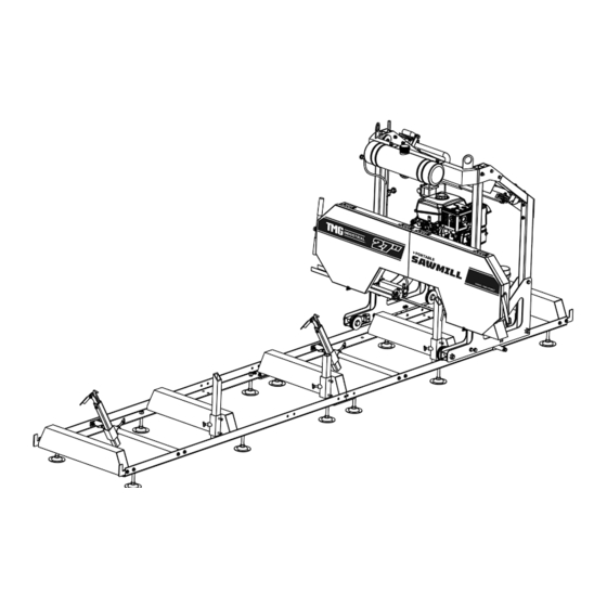
MODEL TMG-PSM27
27" CUTTING CAPACITY
PORTABLE SAWMILL
KOHLER COMMAND PRO SERIES ENGINE
Please read and understand the product manual completely before assembly
Check against the parts list to make sure all parts are received
Wear proper safety goggles or other protective gears while in assembly
Do not return the product to dealer. They are not equipped to handle your requests.
Missing parts or questions on assembly?
Please call: 1-877-761-2819 or email: cs@tmgindustrial.com
Advertisement
Table of Contents

Related Manuals for TMG TMG-PSM27


Summary of Contents for TMG TMG-PSM27
- Page 1 PRODUCT MANUAL V2022.08.05 MODEL TMG-PSM27 27" CUTTING CAPACITY PORTABLE SAWMILL KOHLER COMMAND PRO SERIES ENGINE Please read and understand the product manual completely before assembly Check against the parts list to make sure all parts are received Wear proper safety goggles or other protective gears while in assembly Do not return the product to dealer.
-
Page 2: Table Of Contents
Contents GENERAL SAFETY RULES....................................3 GENERAL MAINTENANCE INFORMATION..............................7 SAWMILL ASSEMBLY INSTRUCTIONS................................8 Inspection.........................................8 Tracks..........................................8 Log Dog & Supports.......................................10 Carriage Assembly......................................12 Electric Wire Connect.....................................24 Engine..........................................25 SAWMILL SET-UP PROCEDURES..................................26 Belt Tension........................................26 Blade Tracking........................................27 Blade Guide Adjustment....................................31 Blade Tension.........................................32 SAWMILL MAINTENANCE.....................................34 Changing the Blade......................................34 Replacing Belts.......................................34 TROUBLESHOOTING......................................36 PART DIAGRAMS......................................37 PARTS LIST........................................39... -
Page 3: General Safety Rules
Thank you very much for choosing the TMG-PSM27 Portable Sawmill. For future reference, please complete the owner’s purchase date: Save the receipt for warranty and these instructions. It is important that you read the entire manual to become familiar with this product before you begin using it. - Page 4 SAVE THESE INSTRUCTIONS WORK AREA Keep work area clean, free of clutter and well lit. Cluttered and dark work areas can cause accidents. Do not use your sawmill where there is a risk of causing a fire or an explosion; e.g. in the presence of flammable liquids, gasses, or dust.
- Page 5 PERSONAL SAFETY Stay alert, watch what you are doing and use common sense when operating a power tool. Donot use a power tool while you are tired or under the influence of drugs, alcohol or medication. A moment of inattention while operating power tools may result in serious personal injury. Dress properly.
- Page 6 corrected before further use. Keep saw blades sharp and clean. Properly maintained band saw blades are less likely to bind and are easier to control. Cleaning and Lubrication. Use only soap and a damp cloth to clean your sawmill. Many household cleaners are harmful to plastic and rubber components on the sawmill.
-
Page 7: General Maintenance Information
MAINTENANCE Proper and routine maintenance is critical to operator safety, achieving good milling results and to prolonging the life of your investment. 1. Band wheel Bearings — Should be inspected before use to ensure they are not worn. Bearings are sealed and do not need to be greased. -
Page 8: Sawmill Assembly Instructions
SAWMILL ASSEMBLY #1 – INSPECTION Take all of the parts out of the shipping crate and lay them out. #2 – TRACKS Assemble track system and secure loosely with provided nuts & bolts. It is important not to fully tighten the bolts at this stage. This will be done after the head is assembled and rolled along the track. - Page 9 2.Attach track cross supports to “L” channel with the provided nuts & bolts. The joining plate is used at the seam joint to join the two sections together (shown in right-down image). Ensure to only hand tighten at this stage. The bolts will be fully tightened once the head assembly is free to roll on the tracks and provide the correct track width.
-
Page 10: Log Dog & Supports
#3 – LOG DOG & SUPPORTS Assemble log dog pieces as shown below and use water proof grease on threaded handle and “T” handle. Attach assembly to the track using the provided nuts & bolts and tighten.Attach log dog assembly to track as shown below with the 4 nuts and bolts provided. - Page 11 We recommend tex screwing the leveling legs to sleepers once the mill has been made level. So before tex screwing the mill to the sleepers, it is highly recommended that you run a string line down both sides of the mill, to make sure the track is straight and level. (The string line is in pink in the above picture).
-
Page 12: Carriage Assembly
#4 – CARRIAGE ASSEMBLY 1.Place a moving blanket on the shipping pallet that the sawmill crate was strapped to. The blanket will prevent the blade guard covers from becoming scratched. Using a minimum of two people or a mechanical advantage system, remove the head assembly from the sawmill crate and place face down on the blanker. The head assembly is very heavy, proper technique must be used to avoid injury or damage. - Page 13 4.Assemble front vertical post to wheel assembly using the two bolts and back plate. Repeat same step for the other front vertical post assembly. Hexagon head bolt: M12x80 Hexagon self-locking nut: M12 Flat washer: Ø12 5.Assemble rear vertical post to wheel assembly using the two bolts and back plate. Repeat same step for the other rear vertical post assembly.
- Page 14 6.Lock the cam handles on both the square post to prevent the head from moving when it is stood up in the coming steps. Ensure that when activating the cam handles, the clamps securely lock on the square vertical post. Press the handle down to lock Quick Lock...
- Page 15 8.Slide the cross beam into the two square tube post. Bolt the top of the square tube post and the cross beam Bolts: M12X70 Flat Washer: Ø12 9.Install the connecting clamping plate, uper arch and steel cable roller,using wrench to hold the nut, tighten the bolt Bolts: M10X80...
- Page 16 B o l t s : M 1 0 X 9 0 F l a t W a s h e r : Ø 1 0 Sp ri ng Wa sh er : Ø 10 H e x N u t : M 1 0 B o l t s : M 1 0 X 3 0...
- Page 17 11.Place the measuring scale assembly, the assembly include ruler and height indicator. A. install ruler,using wrench to hold the nut ,tighten the bolt. B. Install the square indicator rod to the sawmill using the two bolts and tighten. Slide the scale indicator over the square rod and tighten.
- Page 18 12.Install the throttle handle to the round bar as shown in below left image. With the throttle lever in the idle position/fully open, pull the cable tight at the engine and tighten the screw to hold it in place. This will take all of the slack out of the cable. PLEASE NOTE***The idler screw needs to be wound fully out failure to do this will result in the engine not running at its full RPMs’...
- Page 19 14.Install the travel locking device on the travel assembly,using wrench to hold the nut ,tighten the bolt. Hexagon Head Bolt : M8X16 Ø8 Spring Washer: Ø 8 F l a t W a s h e r www.tmgindustrial.com 19/45 Toll Free:1-877-761-2819...
- Page 20 15.Route the cables on both sides as shown in the below image. Short cable, Long cable) ( www.tmgindustrial.com 20/45 Toll Free:1-877-761-2819...
- Page 21 16. The transparent water pipe connects the water tank to the copper connector Please Note: We recommend adding some dishwashing liquid to the tank to help lubricate the wood – two to three capfuls. www.tmgindustrial.com 21/45 Toll Free:1-877-761-2819...
- Page 22 17.Add waterproof grease to the threads of the blade tension “T” handle and to the washer face that it meets before use. Proper blade tension is achieved when the blade deflects no more than a total of 1/8” - 1/4” up/down. *Note –...
- Page 23 19.Push the saw head up and down the track system to ensure that the width of the track allows for the saw head to move freely. If it binds, the “L” rails will need to be set further or closer together to achieve a consistent width along the entire track system.
-
Page 24: Electric Wire Connect
5 – ELECTRIC WIRE CONNECT Step. 1: find the show 1 and 3 connection terminals Step. 2: Disconnect the connection terminals Emergency Step. 3: Find the Emergency Stop Switch and Stop Switch the Microswitch Step. 4: Connect the 1 and 1,2 and 2, 3 and 3 Engine Microswitch Step. -
Page 25: Engine
#6– ENGINE Refer to the engine manual before using your sawmill. Please note that the engine does not contain any petrol or engine oil when it is shipped. Furthermore, the engine is equipped with an oil alert system, meaning that if the crankcase oil level is low or empty, the power is cut to the spark plug and it will not start. -
Page 26: Sawmill Set-Up Procedures
SAWMILL SET-UP PROCEDURES #1 – BELT TENSION To check the belt tension, with your hand, firmly try to deflect the belt up and down. There should be no more than 1/4” of deflection in both directions (1/2” total). If the belt deflects more than this, it will need to be tightened as described below. -
Page 27: Blade Tracking
Now that the engine is free to slide on the engine mounting plate, turn the 16mm nut on the horizontal stud in the clockwise direction. This will pull the engine towards the stud and apply more tension on the belt. Do this step incrementally while checking the belt for proper deflection. - Page 28 Loosen the blade guide assembly bolt with a socket. The round shaft should now be free to slide rearward and out of the way. Perform this step on both guide assemblies. This will ensure that the guide bearings do not influence tracking of the blade while adjusting. Take some tension off of the blade by turning the “T”...
- Page 29 The alignment bolt can now be turned to change the angle of the bandwheel and track the blade. To move the blade more rearward on the bandwheel, this bolt will need to be turned clockwise. Alternatively, turning the bolt in the counter-clockwise direction would force the blade to run more forward on the bandwheel.
- Page 30 Adjusting The Left Hand Side Vertical Bolt Vertical Nut Bottom Bottom Vertical Nut Vertical Bolt To adjust the left side of the sawmill, again start by taking the tension off of the blade by turning the “T” handle one turn in the counter-clockwise direction. Using a 16mm wrench, loosen the “...
-
Page 31: Blade Guide Adjustment
Moving The Blade Rearward Using a 16mm wrench, hold the “horizontal bolt” stationary with a wrench and turn the “horizontal outside nut” counter-clockwise a ½ turn. Still holding the “horizontal bolt” stationary, turn the “horizontal inside nut” clockwise a ½ turn. This step has now shifted the “horizontal bolt” and bandwheel shaft, causing the blade to track more forward. -
Page 32: Blade Tension
Saw Chuck Shaft Seat Saw Block Thickness of a sheet of paper Saw Blade Thickness of a sheet of paper Loosen the blade guide assembly bolt with a 16mm socket. The round shaft should now be free to slide back and forth. Position it so that there is a paper width gap between the bearing and the back of blade. - Page 33 When tensioning the blade, make sure the tracking adjustment bolt sitting behind the T handle (pictured) is sitting back in its recess after you have finished and before the mill is run. Failure to do this will result in the blade being thrown and possibly broken. Tracking adjustment bolt out of recess, of it looks like this DO NOT start the mill until it is resting back in its recess Tracking adjustment bolt sitting in recess.
-
Page 34: Sawmill Maintenance
SAWMILL MAINTENANCE #1 – CHANGING THE BLADE Never attempt the below with the engine running. As a safety precaution, remove the spark plug cap. Gloves and safety glasses must be worn when changing the blade. Remove the tension in the blade by turning the “T” handle in the counter-clockwise direction and then open the blade guard cover. - Page 35 Remove the tension in the blade by turning the “T” handle in the counter-clockwise direction and then open the blade guard cover. The blade should now be loose and free to pull straight out the front. To change the drive side belt, loosen the four bolts that secure the engine to the engine mount using a 16mm wrench.
-
Page 36: Troubleshooting
TROUBLESHOOTING Problem/Issue Possible Causes Resolution Options Inadequate blade Tighten blade. Refer to page 32. Producing wavy tension. cuts. Gap between guide blocks and blade are Improper blade guide incorrect. Refer to page 31. set up. Adjust blade tracking. Refer to page 27. Improper blade tracking. -
Page 37: Part Diagrams
Blade is slowing Inadequate blade Tighten blade. Refer to page 32. tension. Belts are worn or too loose. Replace. Refer to page down or stopping Improper drive belt when Slow feed rate down and push head slower through tension. milling. log. - Page 38 DIAGRAM (A) --BANDWHEEL HOUSEING www.tmgindustrial.com 38/45 Toll Free:1-877-761-2819...
-
Page 39: Parts List
PARTS LIST (A) -- BANDWHEEL HOUSING PART NO. DESCRIPTION PART NO. DESCRIPTION Saw blade Cross pan head screw M6X16 BX2007 Li V- belt spring washer Ø 6 BX1473 Li V-belt Left cover door welding Hexagon head bolt M10X25 Shield body welding Spring washer Ø... - Page 40 PARTS LIST (A) -- BANDWHEEL HOUSING (CONT) PART NO. DESCRIPTION PART NO. DESCRIPTION Hexagon head bolt M12X45 Guide square tube Hex Nut M12 Triangle handle M10X40X30 Hexagon head bolts full thread Beam welding M12X100 Large washer 12 ( Ø 12*35*3.0) Hex Nut M16 Active saw wheel shaft Hexagon head bolt M16X80...
- Page 41 PARTS LIST (B) --CARRIAGE www.tmgindustrial.com 41/45 Toll Free:1-877-761-2819...
- Page 42 PARTS LIST (B) --CARRIAGE PART NO. DESCRIPTION PART NO. DESCRIPTION Hexagon head bolt M12X75 half 13 hole handle wire Spring washer Ø 12 Knob plunger assembly Flat washer Ø 12 Hexagon head bolt M6X16 Clamping plate Rocker welding Upper beam welding Elastic cylindrical pin 5X24 Hex Nut M10 Round nut M14X1.5...
- Page 43 PARTS LIST (B) --CARRIAGE (CONT) PART NO. DESCRIPTION PART NO. DESCRIPTION Flat washer Ø 4 Limit welding Spring washer Ø 4 Small Compression Spring Cross recessed pan head screw Limit shaft M4X12 Hexagon head bolt M12X30 Wire rope brush 7001-230040 Pulley 2 Splint 2 7001-240030 Spacer 1 Hexagon head bolt M6X20...
- Page 44 DIAGRAM (C) --GUIDE RAIL www.tmgindustrial.com 44/45 Toll Free:1-877-761-2819...
- Page 45 PARTS LIST (C) -- GUIDE RAIL PART NO. DESCRIPTION PART NO. DESCRIPTION Hexagon flange bolts M10*30 Log support Guide rail Two-hole guide rail beam welding Limit plate T-screw M10*40 Hexagon flange self-locking nuts Log clamp receiver Hex nut M16 Slide tube Leveling Feet M16 Sliding socket welding Hook...
Need help?
Do you have a question about the TMG-PSM27 and is the answer not in the manual?
Questions and answers