Table of Contents
Advertisement
Quick Links
H-IM-81E
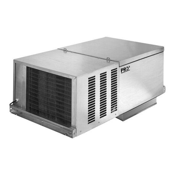
Packaged Refrigeration System
September 2010
PRO
Top Mount
3
For Indoor Applications
Installation and
Operations Manual
Part No. 25001801
Table of Contents
1. Owner's Installation Instructions
Specifications ....................................................................................2
Dimensional Diagrams ..................................................................3
Recommended Unit Placement .................................................4
Mounting............................................................................................5
Standard Installation Procedure ................................................6
2. Controllers
Controllers and Program Settings ...................................... 7-17
3. Service Information
System Troubleshooting Chart ................................................ 18
Replacement Parts ....................................................................... 19
4. Wiring Information
Electrical Wiring Diagrams ..................................................20-25
5. Warranty Information ........................................................ 26
© 2010 Heatcraft Refrigeration Products, LLC
Advertisement
Table of Contents

Subscribe to Our Youtube Channel
Related Manuals for Heatcraft Refrigeration Products PRO3 Top Mount H-IM-81E


Summary of Contents for Heatcraft Refrigeration Products PRO3 Top Mount H-IM-81E
-
Page 1: Table Of Contents
Standard Installation Procedure ..........6 2. Controllers Controllers and Program Settings ........7-17 3. Service Information System Troubleshooting Chart ..........18 Replacement Parts ............... 19 4. Wiring Information Electrical Wiring Diagrams ..........20-25 5. Warranty Information ............26 © 2010 Heatcraft Refrigeration Products, LLC... -
Page 2: Performance/Electrical Data Specifications
Installation and Operations Manual PERFORMANCE / ELECTRICAL DATA TABLE 1 Cooler Air Defrost Systems Refrig. Total Approx. Net BTUH @95°F Charge Heat of Matching Weight Unit Evaporator Plug R-404A Rejection Model Voltage MCA MOPD NEMA Fig. Amps Supplied 35° F Box 38°... -
Page 3: Dimensional Diagrams
Top Mount Packaged Refrigeration System | Indoor DIMENSIONAL DIAGRAMS Small Figure A. Cabinet Dimensions (See Reference on page 2) " x 20 " panel opening required for evaporator section of small cabinet sizes. Medium Figure B. Cabinet Dimensions (See Reference on Page 2). 25"... -
Page 4: Space And Location Requirements
Installation and Operations Manual Space and Location Requirements Recommended Unit Placement For PTN models. The most important consideration which must be taken into account Some general rules for the evaporator section placement which when deciding upon the location of air-cooled equipment is the provision must be followed are: for a supply of ambient air to the condensing unit. -
Page 5: Rigging
Top Mount Packaged Refrigeration System | Indoor Rigging Mounting Rigging holes are provided on all medium and large cabinet The system requires an opening in the ceiling to the dimen- models. Caution should be exercised when moving these sions stated on page 3. Mounting rails are located at both units. -
Page 6: Inspection
8. Complete warranty return card for each unit and mail to 11. Connect unit to power supply using the cord with plug, if Heatcraft Refrigeration Products. provided, or hard wire. Adhere to local electrical/wiring codes. IMPORTANT: General Safety Information •... -
Page 7: Controllers And Program Settings
Top Mount Packaged Refrigeration System | Indoor Refrigeration/Defrost Sequence of Operation The sequence of operation varies depending on the model that has been installed. The three basic models are Low Temperature, Medium Temperature, and High Temperature models. The particular model can be determined by the seventh digit of the model number. See Tables 1-3 for details and settings. - Page 8 Installation and Operations Manual TABLE 6 Model PTN | Medium Temperature Models | EZY SETTING =2 SET POINT IS 34° F These models are intended for cooler applications and have electric defrost. These models are intended for coolers that may be operated at a lower saturated suction temperature and require electric defrost to clear the coil.
- Page 9 Top Mount Packaged Refrigeration System | Indoor Programming the PJEZC Carel Installation and Removal Electronic Controller PANEL INSTALLATION FROM THE FRONT USING SCREWS • The thickness of the fastening panel must not exceed 3 mm; Reprinted with permission from Carel. •...
- Page 10 Installation and Operations Manual Electrical Connections Display WARNINGS: The electrical connections must only be completed by a qualified electrician; A power supply other than the type specified may seriously damage the system; Separate as much as possible the probes and digital input signal cables from the cables carrying inductive loads and power cables to avoid possible electromagnetic disturbance.
- Page 11 Top Mount Packaged Refrigeration System | Indoor Keypads Preliminary Configurations Once the electrical connections have been completed, simply power-up the controller to make it operative. Heatcraft recommends that you check the parameters listed. Control Parameters set point set point differential Defrost Parameters type of defrost NORMAL OPERATION...
- Page 12 Installation and Operations Manual WARNING: When first connected, easy is already on and /5: select °C/°F ready to be used. The instrument can be switched on from Defines the unit of measure used for temperature control. a supervisor PC and via an external contact (setting A4= /5=0 to work in °C 5).
- Page 13 Top Mount Packaged Refrigeration System | Indoor Rapid Parameter Set Selection (EZY) NOTE: The easy controller features the EZY parameter which is used to • to restore the selected rapid parameter set at any time, turn the quickly choose a list of parameters, with corresponding values, for controller off and on again, while holding SET.
- Page 14 Installation and Operations Manual Description of the Main Signals Ed flashing and Alarms The last defrost ended after exceeding the maximum duration rather than when reaching the end defrost set point. LED flashing • check parameters dt, dP and d4; The activation of the corresponding function is delayed by a timer, •...
- Page 15 Top Mount Packaged Refrigeration System | Indoor Modifying the Parameters PARAMETER NAVIGATION The operating parameters, modifiable using the keypad, are divided into two types: frequent (type F) and configuration (type C). Access to the latter is protected by password (default= 22) to prevent accidental or unauthorized modifications.
- Page 16 Installation and Operations Manual Troubleshooting The following table shows a number of situations that may occur on the various models. The most frequent causes and corresponding checks are described: Problem Cause Checks the compressor does not start (signalled by • compressor delay set defrost post parameters c0, c1 and c2 and dd the compressor LED flashing) •...
- Page 17 Top Mount Packaged Refrigeration System | Indoor Device Setup Set 1 - Low Temperature Models - L6 w/ -10° F Set Point Set o Set 1 Set 2 Set 3 Set 4 Parameter Description Default Set point Minimum set point value Maximum set point value Minimum compressor off time Type of Defrost...
-
Page 18: System Troubleshooting Chart
Installation and Operations Manual Table 8. System Troubleshooting Chart PROBLEM POSSIBLE CAUSES POSSIBLE CORRECTIVE STEPS Compressor 1. Main switch open. 1. Close switch. will not run 2. Fuse blown. 2. Check electrical circuits and motor winding for shorts or grounds. Investigate for possible overloading. -
Page 19: Replacement Parts
Heatcraft Refrigeration Products equipment. At InterLink, we provide our wholesalers with a comprehensive selection of product solutions and innovative technologies for the installed customer base. And every product is built to ensure the same high performance standards with which all Heatcraft Refrigeration brands are built —... -
Page 20: Electrical Wiring Diagrams
Installation and Operations Manual Small Cabinet Models Wiring. 230/1/60/ Cooler/Freezer- Electric Defrost Diagram 1. Wiring Diagram for System, Electric Defrost Low /Medium Temperature Wiring. - Page 21 Top Mount Packaged Refrigeration System | Indoor Small Cabinet Models Wiring. 115/1/60 voltage. Air Defrost Systems Diagram 2. Wiring Diagram for System, Air Defrost 115/1/60 model High Temperature Wiring.
- Page 22 Installation and Operations Manual Diagram 3. Wiring Diagram for System, Electric Defrost Medium/Low Temperature Wiring.
- Page 23 Top Mount Packaged Refrigeration System | Indoor Diagram 4. Wiring Diagram for System, Electric Defrost 115/1/60 model Low Temperature Wiring.
- Page 24 Installation and Operations Manual Diagram 5. Wiring Diagram for System Air Defrost 115/1/60 model High Temperature Wiring.
- Page 25 Top Mount Packaged Refrigeration System | Indoor Diagram 6. Wiring Diagram for System, Electric Defrost 115/1/60 model Medium Temperature Wiring.
-
Page 26: Warranty Information
Buyer via lowest common be +/- 10% of nameplate carrier, or Heatcraft Refrigeration Products LLC may at its option grant ratings. Single phase must be Buyer a credit for the purchase price of the defective article. Upon... - Page 27 Top Mount Packaged Refrigeration System | Indoor Notes:...
- Page 28 The name behind the brands you trust. Heatcraft Refrigeration Products, LLC 2175 West Park Place Blvd., Stone Mountain, GA 30087 P: (800) 321-1881 • www.heatcraftrpd.com Since product improvement is a continuing effort, we reserve the right to make changes in specifications without notice.
Need help?
Do you have a question about the PRO3 Top Mount H-IM-81E and is the answer not in the manual?
Questions and answers