StepperOnline CL86T (V4.0) - Closed Loop Stepper Driver Manual
- User manual (12 pages)
Advertisement
Record of Revisions
| Revision | Date | Description of Release |
| 1.00 | Aug, 2019 | Initial Release |
| 4.00 | Oct, 2020 | Add rotating switch, 5/24V selector switch, brake output. |
Features
- Input voltage 18-80VAC or 24-110VDC
- No loss of step, No tuning
- 500 KHz max pulse input frequency
- Resolutions of 200-51,200 via DIP switches SW1 - SW4
- 2 out current settings and gain tuning via S1 rotating switch
- Optically isolated inputs with 5V or 24V l Motor rotating direction setting by SW5
- Closed loop or open loop control setting by SW6
- Step&Direction or CW&CCW pulse type setting by SW7 l Configure position reach output or brake output by SW8
- Over-voltage, over-current protections, position following error, etc
Specifications
Electrical Specifications
| Parameters | Min | Typical | Max | Unit |
| Peak Current | 5.6A (RMS 4A) | 7A (RMS 5A) | 8A (RMS 5.7A) | A |
| Operating Voltage | 18 24 | - | 80 110 | VAC VDC |
| Logic input signal current | 7 | 10 | 20 | mA |
| High speed pulse input frequency (5V) | 0 | - | 500 | kHz |
| Pulse input frequency (24V) | 0 | - | 200 | kHz |
| Input signal voltage | 5 | - | 24 | VDC |
| Logic current output | - | - | 100 | mA |
Environment
| Cooling | Natural Cooling or Forced Cooling | |
| Operating Environment | Environment | Avoid dust, oil fog and corrosive gases |
| Humidity | 40%RH-90%RH | |
| Operating Temperature | 0°C - 40°C (32°F - 102°F) | |
| Vibration | 10-50Hz / 0.15mm | |
| Storage Temperature | -20°C - 65°C (-4°F - 149°F) | |
| Weight | Approx. 600g | |
Mechanical Specifications
(unit: mm [1inch=25.4mm])

Figure 1: Mechanical specifications
Heat Dissipation
- CL86T(V4.0) reliable working temperature should be no more than 40℃ (109°F)
- It is recommended to mount the drive vertically to maximize heat dissipation. Mount a cooling fan nearby if necessary.
- If multiple CL86T (V4.0) drives are installed, it is suggested to keep a minimal 30mm (12 inches) between two of them.
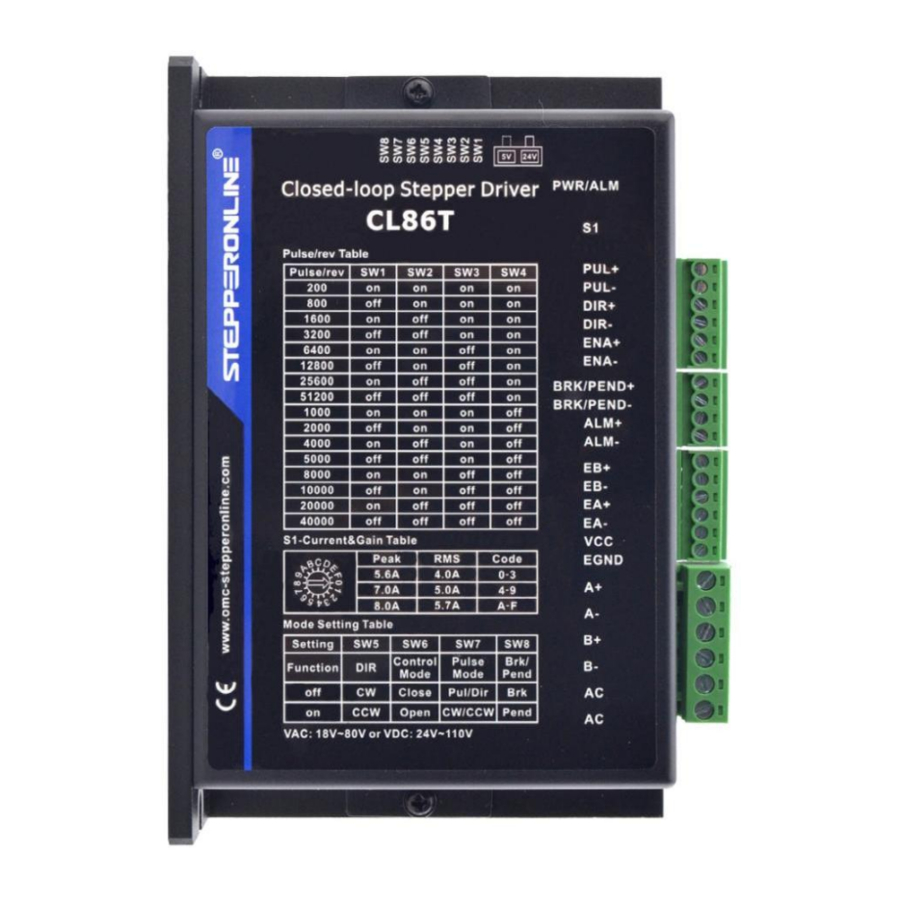
Connections and LED Indication
Control and Digital Output Connections
| PIN | I/O | Details |
| PUL+ (CW+) | I | Pulse and Direction Connection:
|
| PUL- (CW-) | I | |
| DIR+ (CCW+) | I | |
| DIR- (CCW-) | I | |
| ENA+ | I | Enable Signals: Optional.
|
| ENA- | I | |
| BRK+ (PEND+) | O | Select brake output or pend output by switch 8, default as brake output Max 30VDC/100mA |
| BRK- (PEND-) | O | |
| ALM+ | O | Max 30VDC/100mA |
| ALM- | O |
 Notes:
- Shielding control signal wires is suggested;
- To avoid/reduce interference, don't tie control signal cables and power wires together;
- Brake output need to connect a relay and diode
Encoder Signals Input Connector
| Drive Pin Name | Description |
| EB+ | Encoder B+ input connection |
| EB- | Encoder B- input connection |
| EA+ | Encoder A+ input connection |
| EA- | Encoder A- input connection |
| VCC | Encoder +5V voltage output connection |
| EGND | Power ground connection |
Motor Connector
| PIN | Details |
| A+ | Connect to motor A+ wire |
| A- | Connect to motor A- wire |
| B+ | Connect to motor B+ wire |
| B- | Connect to motor B- wire |
| AC | Available for AC input or DC input, no polarity request while DC input |
| AC |
LED Status Lights
There are two LED lights. The GREEN one is the power indicator which should be always on in normal circumstance. The RED one is a alarm status indication light, which will be OFF while working normally but ON and flash some times in a 3-second period in the case of enabled alarm protections.
Power Supply Selection
The CL86T (V4.0) can power medium and large size stepping motors (frame size from NEMA 17 to 24). To get good driving performances, it is important to select supply voltage and output current properly. Generally speaking, supply voltage determines the high speed performance of the motor, while output current determines the output torque of the driven motor (particularly at lower speed). Higher supply voltage will allow higher motor speed to be achieved, at the price of more noise and heating. If the motion speed requirement is low, it's better to use lower supply voltage to decrease noise, heating and improve reliability.
Power Supply Sharing
Multiple CL86T (V4.0) drives can share one power supply to reduce cost, if that power supply has enough power capacity. To avoid cross interference, connect each stepper drive directly to the shared power supply separately. To avoid cross interference, DO NOT daisy-chain connect the power supply input pins of the drivers. Instead connect them to power supply separately.
Selecting Supply Voltage
The CL86T (V4.0) is designed to operate within 24 - 110VDC or 18 - 80VAC voltage input. When selecting a power supply, besides voltage from the power supply power line voltage fluctuation and back EMF voltage generated during motor deceleration needs also to be taken into account. Please make sure leaving enough room for power line voltage fluctuation and back-EMF voltage charge back.
Higher supply voltage can increase motor torque at higher speeds (>300 RPM), thus helpful for avoiding losing steps. However, higher voltage may cause bigger motor vibration at lower speed, and it may also cause over-voltage protection or even drive damage.
Switch Configurations
Rotating Switch Configurations
This rotating switch is used to set the peak current of the drive and motion gain, from the motor phase current and application requirements.
 | Peak Current | Code | Velocity loop Ki | Position loop Kp | Velocity loop Kp |
| 5.6A | 0 (factory) | 0 | 25 | 25 | |
| 1 | 0 | 50 | 15 | ||
| 2 | 16 | 25 | 25 | ||
| 3 | 16 | 50 | 15 | ||
| 7.0A | 4 | 0 | 25 | 25 | |
| 5 | 0 | 50 | 15 | ||
| 6 | 0 | 100 | 5 | ||
| 7 | 16 | 25 | 25 | ||
| 8 | 16 | 50 | 15 | ||
| 9 | 16 | 100 | 5 | ||
| 8.0A | A | 0 | 25 | 25 | |
| B | 0 | 50 | 15 | ||
| C | 0 | 100 | 5 | ||
| D | 16 | 25 | 25 | ||
| E | 16 | 50 | 15 | ||
| F | 16 | 100 | 5 |
 Remark:
- Velocity loop Ki Indicates the stop time and position accuracy, "0" indicates the stop time is long, but the position error is smaller."16" means the stop time is short, but the position error is slightly larger.
- Position loop Kp and velocity loop Kp is a pair of composite parameters that represent rigidity. "25" and "25"composite parameters indicate the rigidity is weak, "100" and "5"composite parameters indicate the rigidity is strong. Sometimes if the motor will rotate after stopping, it can increase the value of position loop Kp, but if the value is too large, the motor will have noise.
- Usually keep factory settings
DIP Switch Configurations
The 8-bit is located on the side and used to configure settings of micro step resolution, output current, and motor standstill current as shown below

Figure 2: DIP switches
Micro Step (SW1-SW4)
Each CL86T (V4.0) has 16 microstep settings which can be configured through DIP switches SW1, SW2, SW3 and SW4. See the following table for detail.
| Micro step | Pulses/Rev. (for 1.8°motor) | SW1 | SW2 | SW3 | SW4 |
| 1 | 200 (Default) | on | on | on | on |
| 4 | 800 | off | on | on | on |
| 8 | 1600 | on | off | on | on |
| 16 | 3200 | off | off | on | on |
| 32 | 6400 | on | on | off | on |
| 64 | 12800 | off | on | off | on |
| 128 | 25600 | on | off | off | on |
| 256 | 51200 | off | off | off | on |
| 5 | 1000 | on | on | on | off |
| 10 | 2000 | off | on | on | off |
| 20 | 4000 | on | off | on | off |
| 25 | 5000 | off | off | on | off |
| 40 | 8000 | on | on | off | off |
| 50 | 10000 | off | on | off | off |
| 100 | 20000 | on | off | off | off |
| 200 | 40000 | off | off | off | off |
Mode Setting (SW5 - SW8)
| Function | ON | OFF | |
| SW5 | Rotation Direction | CW (clockwise) | CCW (counterclockwise) |
| SW6 | Control Mode | Open loop control | Closed loop control |
| SW7 | Pulse Mode | CW/CCW (double pulse) | PUL/DIR (single pulse) |
| SW8 | Brake/ pend | Pend output | Brake output |
Typical Connection
Digital Input Connection
The CL86T (V4.0) can accept can accept differential or single-ended control signals (pulse, direction, and enable) in open-collector or PNP connection. It is recommend to add an EMI line filter between the power supply and the drive to increase noise immunity for the drive in interference environments.

Figure 3: Connections to open-collector signal
(Common-anode)

Figure 4: Connections to PNP signal
(Common-cathode)
Notes:
- ENA signal is no-connected as default;
- ENA signal is no connected as default, and ENA signal is available for 5V~24V.
Fault Output Connection
When over voltage or over current protection happens, CL86T(V4.0) red status LED light will blink and the impedance state between ALM+ and ALM- will change (from low to high or high to low depending on configuration) and can thus be detected. Fault output connection is optional, and it can be connected either in sinking or sourcing.
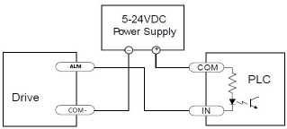
Connecting a sinking output to a PLC's input
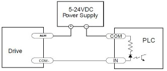
Connecting a sourcing output to a PLC's input
Brake Output Connection
This drive has a special brake output; it needs to drive the motor brake with a relay. The connection is below:

Figure 7:Brake output connection
Sequence Chart of Control Signals
In order to avoid some fault operations and deviations, PUL, DIR and ENA should abide by some rules, shown as following diagram:

Figure 8: Sequence chart of control signals
Remark:
- t1: ENA must be ahead of DIR by at least 200ms. Usually, ENA+ and ENA- are NC (not connected).
See "Connector P1 Configurations" for more information. - t2: DIR must be ahead of PUL effective edge by 2us to ensure correct direction;
- t3: Pulse width not less than 1us;
- t4: Low level width not less than 1us;
- Duty cycle of PUL signal is recommended 50%.
Fault Protections & Troubleshooting
To improve reliability, the drive incorporates some built-in protection features.
| Blink time(s) | Sequence wave of red LED | Description | Trouble shooting |
| 1 |  | Over-current | Turn off the power immediately.
|
| 2 |  | Over-voltage | Turn off the power immediately.
|
| 3 |  | Chip error | Restart the power supply, if the drive is still alarm, please contact after-sale |
| 4 |  | Fail to lock motor shaft |
|
| 5 |  | EEPROM error | Restart the power supply, if the drive is still alarm, please contact after-sale |
| 6 |  | Fail to auto tuning | Restart the power supply, if the drive is still alarm, please contact after-sale |
| 7 |  | Position following error |
|
| Always | - | PCB board is burned out | Restart the power supply, if the drive is still alarm, please contact after-sale |
When above protections are active, the motor shaft will be free or the red LED blinks. Reset the drive by repowering it to make it function properly after removing above problems.
In the event that your drive doesn't operate properly, the first step is to identify whether the problem is electrical or mechanical in nature. The next step is to isolate the system component that is causing the problem. As part of this process you may have to disconnect the individual components that make up your system and verify that they operate independently. It is important to document each step in the troubleshooting process. You may need this documentation to refer back to at a later date, and these details will greatly assist our Technical Support staff in determining the problem should you need assistance.
Many of the problems that affect motion control systems can be traced to electrical noise, controller software errors, or mistake in wiring.
| Symptoms | Possible Problems | Solutions |
| Motor is not rotating | No power | Connect power supply correctly |
| Microstep resolution setting is wrong | Setting appropriate microstep | |
| Fault condition exists | Check wiring and restart power | |
| The drive is disabled | Drive restore factory setting, and keep ENA+, ENA- input signals unconnected. | |
| Wrong motor rotation direction | The Direction signal level is reverse | Toggling the SW5 DIP switch |
| Erratic motor motion | Control signal is too weak | Ensure the current of control signal is within 7-16mA |
| Control signal is interfered | Don't tie the control signal cable with power cable together | |
| Wrong motor connection | Refer to user manual of drive and motor datasheet | |
| Something wrong with motor coil | Check the motor is normal | |
| Motor stalls during acceleration | Current setting is too small | Choose another power supply with lager power or increase the output current of drive |
| Motor is undersized for the application | Choose another motor with higher torque | |
| Acceleration is set too high | Reduce the acceleration | |
| Power supply voltage too low | Choose another power supply with large voltage output | |
| Excessive motor & drive heating | Inadequate heat sinking / cooling | Refer to Heat Dissipation chapter |
| Motor peak current setting is too high | Reduce the current value refer to motor datasheet | |
| Motor vibration when power on | Speed loop Kp is too high | Reduce the speed loop Kp value |

Documents / ResourcesDownload manual
Here you can download full pdf version of manual, it may contain additional safety instructions, warranty information, FCC rules, etc.
Download StepperOnline CL86T (V4.0) - Closed Loop Stepper Driver Manual
Advertisement


Need help?
Do you have a question about the CL86T and is the answer not in the manual?
Questions and answers