
Related Manuals for StepperOnline DM542T


Summary of Contents for StepperOnline DM542T
- Page 1 User Manual DM542T(V4.0) 2-Phase Digital Stepper Drive Revision 4.0 Record of Revisions Revision Date Description of Release Dec, 2016 Initial Release Oct., 2020 Add 5V/24V logical voltage selector, alarm outputs...
-
Page 2: Table Of Contents
Table of Contents 1. Features.....................................1 2. Specifications..................................1 2.1 Electrical Specifications............................1 2.2 Environment................................1 2.3 Mechanical Specifications............................2 2.4 Elimination of Heat..............................2 3. Connection Pin Assignments and LED Indication......................2 3.1 P1 - Control Connector............................3 3.2 P2 - Fault and Brake Output Connector......................... 3 3.3 P3 - Motor and Power Supply Connector.......................3 3.5 LED Light Indication.............................. -
Page 3: Features
DM542T(V4.0) Digital Stepper Drive User Manual 1. Features Step & direction (PUL/DIR) control Input voltage 20-50VDC (recommended 24-48VDC) 200 KHz max pulse input frequency 16 microstep resolutions of 200-25,600 via DIP switches 8 output current settings of 1.0-4.5A via DIP Switches ... -
Page 4: Mechanical Specifications
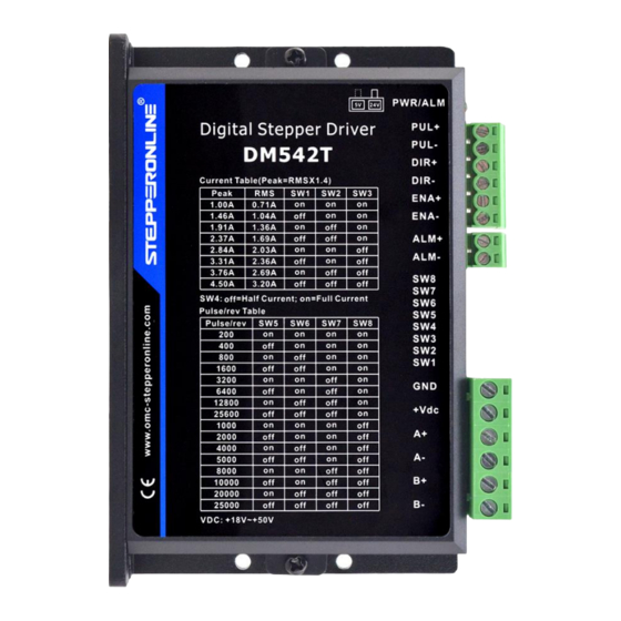
Connectors, DIP switches, and LED locations The DM542T(V4.0) has three connector blocks P1&P2&P3 (see above picture). P1 is for control signals connections, and P2 is for output signals connections, P3 is for power and motor connections. The following tables are brief... -
Page 5: P1 - Control Connector
3.4 LED Light Indication There are two LED lights for DM542T(V4.0). The GREEN one is the power indicator which will be always on generally. The RED one is a protection indicator which will flash 1-2 times in a 3-second period, when protection enabled for a... -
Page 6: Control Signal And Output Signal
4.2 Fault Output Connection When over voltage or over current protection happens, DM542T(V4.0) red status LED light will blink and the impedance state between ALM+ and ALM- will change (from low to high or high to low depending on configuration) and can thus be detected. -
Page 7: Power Supply Selection
7. DIP Switch Configurations The DM542T(V4.0) has one 8-bit DIP switch and one 1-bit selector. The first 8-bit is used to configure settings of micro step resolution, output current, motor standstill current, pulse type and smoothing time as shown below. -
Page 8: Output Current Configurations
DM542T(V4.0) Digital Stepper Drive User Manual Microstep resolution is set by SW5, 6, 7, 8 of the DIP switches as shown in the following table. Microstep Steps/rev.(for 1.8°motor) 1600 3200 6400 12800 25600 1000 2000 4000 5000 8000 10000 20000 25000 7.2 Output Current Configurations... -
Page 9: Idle Current Configuration
The current automatically reduced to 50% of the selected dynamic current 0.4 second after the last pulse. 7.3 Automatic Motor Matching & Self Configuration When powered on a DM542T(V4.0) will automatically configure itself with the best settings to match the driven stepper motor for optimal performance. No action is needed. -
Page 10: Sequence Chart Of Control Signals
DM542T(V4.0) Digital Stepper Drive User Manual 10. Sequence Chart of Control Signals In order to avoid some fault operations and deviations, PUL, DIR and ENA should abide by some rules, shown as following diagram: Figure 15: Sequence chart of control signals Remark: t1: ENA must be ahead of DIR by at least 200ms. -
Page 11: Troubleshooting
DM542T(V4.0) Digital Stepper Drive User Manual 12. Troubleshooting In the event that your drive doesn’t operate properly, the first step is to identify whether the problem is electrical or mechanical in nature. The next step is to isolate the system component that is causing the problem. As part of this process you may have to disconnect the individual components that make up your system and verify that they operate independently.
Need help?
Do you have a question about the DM542T and is the answer not in the manual?
Questions and answers
Hello, I **** trying to wire a stepperonline driver DM542T. I cant find the male connectors to use. Could you tell me if you have them or do you know what they are called?
The StepperOnline DM542T driver has two main connectors for wiring:
- Connector P1 for control signals
- Connector P2 for power and motor wiring
This answer is automatically generated