Table of Contents
Advertisement
User's Manual
For
DM542T
Full Digital Stepper Drive
Designed by StepperOnline®
Manufactured by Leadshine®
©2017 All Rights Reserved Attention: Please read this manual
carefully before using the drive!
#7 Zhongke Road, Jiangning, Nanjing, China
T: 0086-2587156578
Web site:
www.omc-stepperonline.com
E-Mail:sales@stepperonline.com
Advertisement
Table of Contents

Related Manuals for StepperOnline DM542T


Summary of Contents for StepperOnline DM542T
- Page 1 User’s Manual DM542T Full Digital Stepper Drive Designed by StepperOnline® Manufactured by Leadshine® ©2017 All Rights Reserved Attention: Please read this manual carefully before using the drive! #7 Zhongke Road, Jiangning, Nanjing, China T: 0086-2587156578 Web site: www.omc-stepperonline.com E-Mail:sales@stepperonline.com...
-
Page 2: Table Of Contents
Table of Contents 1. Introductions, Features and Applications........................1 Introductions................................1 Features..................................1 Applications.................................1 2. Specifications.................................. 1 Electrical Specifications (T = 25℃/77℉)......................... 1 Operating Environment and other Specifications.......................2 Mechanical Specifications (unit: mm [1inch=24.5mm])....................2 Elimination of Heat..............................2 3. Pin Assignment and Description............................. 3 Connector P1 Configurations............................3 Connector P2 Configurations............................3 4. -
Page 3: Introductions, Features And Applications
1. Introductions, Features and Applications Introductions The DM542T is a fully digital stepper drive developed with advanced DSP control algorithm based on the latest motion control technology. It has achieved a unique level of system smoothness, providing optimal torque and nulls mid- range instability. -
Page 4: Operating Environment And Other Specifications
DM542T Full Digital Stepper Drive Manual V2.0 Operating Environment and other Specifications Cooling Natural Cooling or Forced cooling Environment Avoid dust, oil fog and corrosive gases 0℃ - 65℃ Ambient Temperature 40%RH-90%RH Operating Environment Humidity -10℃ - 45℃ Operating Temperature 10-50Hz / 0.15mm... -
Page 5: Pin Assignment And Description
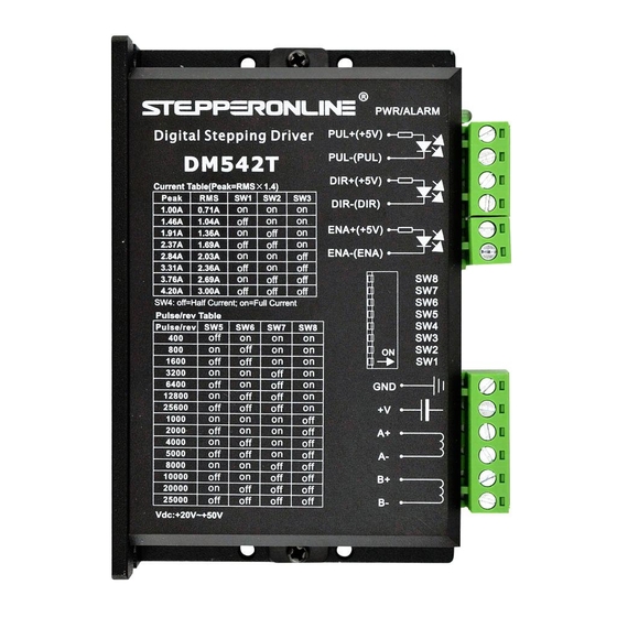
3. Pin Assignment and Description The DM542T has two connectors P1&P2, P1 is for control signals connections, and P2 is for power and motor connections. The following tables are brief descriptions of the two connectors. More detailed descriptions of the pins and related issues are presented in section 4, 5, 9. -
Page 6: Connections Of 4-Lead Motor
DM542T Full Digital Stepper Drive Manual V2.0 Drive Controller Controller Drive PUL+ PUL+ PUL- PUL- DIR+ DIR+ DIR- DIR- ENA+ ENABLE ENA+ ENA- ENA- ENABLE Figure 2: Connections to open-collector Figure 3: Connections to PNP signal (common-cathode) signal (common-anode) Connections of 4-lead Motor The 4 lead motors are the least flexible and easy to connect. -
Page 7: Full Coil Configurations
DM542T Full Digital Stepper Drive Manual V2.0 Full Coil Configurations The full coil configuration on a six lead motor should be used in applications where higher torque at lower speed is desired. This configuration is also referred to as full copper. In full coil mode, the motors should be run at only 70% of their rated current to prevent overheating. -
Page 8: Power Supply Selection
V2.0 Power Supply Selection The DM542T can match medium and small size stepping motors (frame size from NEMA17 to 34) made by Leadshine or other motor manufactures around the world. To achieve good driving performances, it is important to select supply voltage and output current properly. Generally speaking, supply voltage determines the high speed performance of the motor, while output current determines the output torque of the driven motor (particularly at lower speed). -
Page 9: Current Settings
DM542T Full Digital Stepper Drive Manual V2.0 Microstep Steps/rev.(for 1.8°motor) 1600 3200 6400 12800 25600 1000 2000 4000 5000 8000 10000 20000 25000 Current Settings For a given motor, higher drive current will make the motor to output more torque, but at the same time causes more heating in the motor and drive. -
Page 10: Standstill Current Setting
DM542T Full Digital Stepper Drive Manual V2.0 Standstill Current Setting SW4 is used for this purpose. OFF meaning that the standstill current is set to be half of the selected dynamic current, and ON meaning that standstill current is set to be the same as the selected dynamic current. -
Page 11: Sequence Chart Of Control Signals
DM542T Full Digital Stepper Drive Manual V2.0 9. Sequence Chart of Control Signals In order to avoid some fault operations and deviations, PUL, DIR and ENA should abide by some rules, shown as following diagram: Figure 10: Sequence chart of control signals Remark: t1: ENA must be ahead of DIR by at least 5s. -
Page 12: Frequently Asked Questions
DM542T Full Digital Stepper Drive Manual V2.0 11.Frequently Asked Questions In the event that your drive doesn’t operate properly, the first step is to identify whether the problem is electrical or mechanical in nature. The next step is to isolate the system component that is causing the problem. As part of this process you may have to disconnect the individual components that make up your system and verify that they operate independently.
Need help?
Do you have a question about the DM542T and is the answer not in the manual?
Questions and answers