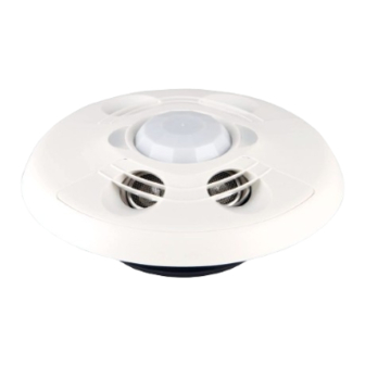
Crestron GLS-ODT-C-CN Installation Manual
Dual-technology occupancy sensor with cresnet, 2000 sq. ft
Hide thumbs
Also See for GLS-ODT-C-CN:
- Installation manual (2 pages) ,
- Product manual (37 pages) ,
- Manual (2 pages)
Table of Contents
Advertisement
Quick Links
Crestron GLS-ODT-C-CN
Dual-Technology Occupancy Sensor with Cresnet
®
Installation Guide
Further Inquiries
To locate specific information or resolve questions after reviewing this guide, contact Crestron's True Blue Support at
1-888-CRESTRON [1-888-273-7876] or, for assistance within a particular geographic region, refer to the listing of
Crestron worldwide offices at www.crestron.com/offices.
To post a question about Crestron products, log onto Crestron's Online Help at www.crestron.com/onlinehelp.
First-time users must establish a user account to fully benefit from all available features.
Future Updates
As Crestron improves functions, adds new features and extends the capabilities of the GLS-ODT-C-CN, additional
information may be made available as manual updates. These updates are solely electronic and serve as
intermediary supplements prior to the release of a complete technical documentation revision.
Check the Crestron Web site periodically for manual update availability and its relevance. Updates are identified as
an "Addendum" in the Download column.
WARNING: To avoid fire, shock, or death; turn off power at circuit breaker or fuse and test that power is off before
wiring!
NOTES: Observe the following points.
•
To be installed and/or used in accordance with appropriate electrical codes and regulations.
•
This product should be installed by a qualified electrician.
•
Sensors must be mounted on a vibration free surface.
PREPARING AND CONNECTING WIRES
Strip the ends of the wires approximately 1/4 in (6 mm). Use care to avoid nicking the conductors. Twist together
the ends of the wires that share a connection. Apply solder only to the ends of the twisted wires. Avoid tinning too
far up the wires or the ends become brittle.
Crestron Electronics, Inc.
Installation Guide - DOC. 7427B
15 Volvo Drive Rockleigh, NJ 07647
Tel: 888.CRESTRON
Fax: 201.767.7576
Specifications subject to
www.crestron.com
change without notice.
This product is Listed to applicable
UL Standards and requirements by
Underwriters Laboratories Inc.
TYPICAL APPLICATION DIAGRAMS
The following diagrams illustrate the typical wiring of a GLS-ODT-C-CN.
Wire GLS-ODT-C-CN
Crestron
Cresnet
2 or 3-Series
Control System or
CLS-C6
Wire GLS-ODT-C-CN with Photocell
Crestron
Cresnet
2 or 3-Series
Control System or
CLS-C6
External
Photocell
DESCRIPTION
, 2000 Sq. Ft.
The Crestron
®
Dual-Technology Occupancy Sensor is a low-voltage passive infrared (PIR)
and ultrasonic (US) sensor that is directly wired through Cresnet
lighting or any other system wide device. The sensor is typically used to turn lights on when a
room or area is occupied and to shut them off when the room or area is vacated. The exact
behavior of the sensor can be configured via software or the IR remote
(GLS-REMOTE-ODT/OIR, sold separately). The combination of ultrasonic motion detection,
which provides maximum sensitivity, and passive infrared motion detection, which provides
higher immunity to false triggering, yields a sensor with a 360 degree 2000 square feet
coverage area with excellent performance. Additionally, a photocell allows for easy and
custom adjustments for even the most robust of daylight harvesting applications.
INSTALLATION
These instructions include two typical ceiling installation options. 1. Install into drop ceiling or
drywall (preferred), or, 2. Install into octagon electrical box.
The following items are included with the GLS-ODT-C-CN for installation:
• 1/2 Solid PIR mask (1)
• 1/12 Perforated PIR mask (1)
• Hole cutout template (1)
The following items are required for installation:
• Slotted/Phillips screwdriver
• Pencil
• Cutting tools
NOTE: Before securing the sensor to the ceiling, rotate the device to ensure it faces the
desired direction. Refer to the "Mounting/Masking Location" and "Detection Range"
sections to choose the best orientation. Avoid areas where false tripping may occur due to
outside motion such as an open door. Identify and avoid areas of possible vibrations and
air currents (e.g., projectors, fans, vents) and mount the sensor at least 5 feet (2 meters)
away from these items.
NOTE: Depending on installation requirements, the ultrasonic sensors on the
GLS-ODT-C-CN can be enabled or disabled through the IR remote. The ultrasonic sensors
are split into two banks—bank A and bank B—which are labeled under the cover of the
sensor. If the sensor is installed and the orientation of the ultrasonic sensors is unknown,
bank A is located on the red LED side of the sensor and bank B is located on the green
LED side of the sensor.
Option 1. Install Into Drop Ceiling or Drywall
1. Select the location for mounting the sensor and proper masking for the application.
2. Use the supplied hole cutout template to mark the ceiling where the sensor is to be
mounted.
3. Use cutting tools appropriate for the surface to create a hole in the ceiling.
4. Turn the sensor cover counterclockwise to separate it from the GLS-ODT-C-CN.
5. Place the GLS-ODT-C-CN into the hole and secure the sensor to the drywall or ceiling
tile using the preinstalled screws. The preinstalled screws have plastic "wings" that
(2034427)
secure the occupancy sensor to the ceiling. When the screws are tightened the wings
08.13
open and clamp against the surface of the ceiling. Refer to the illustration below for a
typical mounting scenario.
Mount GLS-ODT-C-CN to Drywall or Drop Ceiling
GLS-ODT-C-CN
(Cover Removed)
Cover
6. Place the cover on the device and twist to secure. Align the arrows on the device with
the arrows under the cover. Twist the cover clockwise. The cover snaps into place.
Option 2. Install Into Octagon Electrical Box
1. Select the location for mounting the sensor and proper masking for the application.
2. Turn the sensor cover counterclockwise to separate it from the device.
®
to automatically control
3. Using a Phillips screwdriver, unscrew the the preinstalled screws from the plastic wings
and remove them from the sensor.
4. Mount the GLS-ODT-C-CN to the octagon electrical box using two screws (not
supplied).
Mounting to Octagon Electrical Box
Octagon
Electrical
Box
GLS-ODT-C-CN
(Cover Removed)
Mounting Screws
(Not Supplied)
Cover
5. Place the cover on the device and twist to secure. Align the arrows on the device with
the arrows under the cover. Twist the cover clockwise. The cover snaps into place.
MOUNTING/MASKING LOCATION DIAGRAM
The supplied masks mount in the sensor cover to block the PIR sensor. The half mask is
supplied to allow half of the sensor to be masked. The perforated mask has twelve 30º
removable segments that allow masking particular areas to prevent undesireable triggers
from affecteng the sensor operation.
Masking is not required in the corner mounting application shown below because it cannot
see through a door. By masking a portion of the sensor, traffic through a hallway can be
ignored as in the second example. The following illustrations provide typical application
examples.
Ceiling
DETECTION RANGE
High Sensitivity Setting
The detection pattern for the high sensitivity setting is shown in the illustrations below. The
first and second illustration show the side view of the detection range based upon the
sensor orientation. The third illustration shows the detection range based on the top view of
the sensor.
SIDE VIEW A
0 ft (0 m)
Ultrasonic Minor Motion
Ultrasonic Major Motion
PIR Major Motion
8 ft (2.4 m)
8.5 ft (2.6 m)
10 ft (3 m)
12 ft (4 m)
30
25
20
15
10
5
0
5
10
15
20
25
30
(10)
(8)
(6)
(5)
(3)
(2)
(0)
(2)
(3)
(5)
(6)
(8)
(10)
ft
(m)
SIDE VIEW B
0 ft (0 m)
8 ft (2.4 m)
8.5 ft (2.6 m)
10 ft (3 m)
12 ft (4 m)
30
25
20
15
10
5
0
5
10
15
20
25
30
(10)
(8)
(6)
(5)
(3)
(2)
(0)
(2)
(3)
(5)
(6)
(8)
(10)
ft
(m)
Top View
25 (8)
8 1/2 ft (2.6 m)
Ceiling Height
20 (6)
15 (5)
10 (3)
5 (2)
ft (m)
0 (0)
5 (2)
10 (3)
15 (5)
20 (6)
25 (8)
30 (10)
30
25
20
15
10
5
0
5
10
15
20
25
30
(10)
(8)
(6)
(5)
(3)
(2)
(0)
(2)
(3)
(5)
(6)
(8)
(10)
ft
(m)
Advertisement
Table of Contents

Subscribe to Our Youtube Channel
Related Manuals for Crestron GLS-ODT-C-CN


Summary of Contents for Crestron GLS-ODT-C-CN
- Page 1 (e.g., projectors, fans, vents) and mount the sensor at least 5 feet (2 meters) Further Inquiries To locate specific information or resolve questions after reviewing this guide, contact Crestron's True Blue Support at away from these items. (10)
- Page 2 The occupancy sensor should beep when re-entering the room. Crestron shall not be liable to honor the terms of this warranty if the product has been used in any application other than that for which it was intended or if it has been subjected to misuse, accidental 2.
Need help?
Do you have a question about the GLS-ODT-C-CN and is the answer not in the manual?
Questions and answers