Table of Contents
Advertisement
Quick Links
USER'S MANUAL FOR OPERATION OF
THE AUTONOMOUS CONTROL UNIT
(ACU)
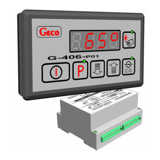
G-406-P01
TO CONTROL CENTRAL HEATING
CULM AND COAL BOILERS WITH
AIR BLOW IN
Program version 05
Please read these instructions very carefully before connecting and starting any of our equipment.
In cases of any doubt, please contact our company between 8:00 a.m - 4:00 p.m.
Advertisement
Table of Contents

Related Manuals for Geco G-406-P01


Summary of Contents for Geco G-406-P01
- Page 1 USER'S MANUAL FOR OPERATION OF THE AUTONOMOUS CONTROL UNIT (ACU) G-406-P01 TO CONTROL CENTRAL HEATING CULM AND COAL BOILERS WITH AIR BLOW IN Program version 05 Please read these instructions very carefully before connecting and starting any of our equipment.
-
Page 2: Table Of Contents
Configuration of User's parameters....................8 6.1. Preset temperature of outlet water (u0) ................8 6.2. Preset temperature of boiler water (u1) ................9 USING THE D.H.W. TANK .......................9 7.1. Installation and connection....................9 7.2. Parameter configuration ....................11 CONNECTING THE UNIT TO CONTROLLER G-406-P01: ..........12 TROUBLESHOOTING ......................15... -
Page 3: General
DHW pump and supply fan of 230V power supply with current consumption as per table 1. The signal lamp on the module informs of the power and fuse status. G-406-P01 does not require special maintenance. The console is made of special foil resistant to high temperatures and most chemical agents. -
Page 4: Operation And Adjustments Of The G-406-P01
Gain factors for protection from increase above the preset values in the stack are set permanently 3. Minimum stack temperature maintained by G-406-P01 depends on by how many C the water in the boiler exceeds the water temperature set by the user (preset {T }) . -
Page 5: Using G-406-P01
3 to 4. • Within the time from pressing the light-up button until fuel burns down in the boiler the controller does not require any attendance. PPUH „GECO” Sp. z o.o. G-406-P01-U-v05a-w01 2005-09-20... -
Page 6: Manual And Automatic Control Of C.h. Pump
2°C increment. After preview time is over the display automatically returns to indication of outlet water temperature. If the stack sensor gets broken message AL3 is displayed for seconds every seconds stack temperature preview inhibited. PPUH „GECO” Sp. z o.o. G-406-P01-U-v05a-w01 2005-09-20... -
Page 7: Indication Of Fan Operation
If additional DHW pump is not used an alarm bell can be connected to the auxiliary output. This output is turned on for 2 seconds, and then turned off for 2 seconds, and so on... PPUH „GECO” Sp. z o.o. G-406-P01-U-v05a-w01... -
Page 8: Supply Voltage Loss
• If no button is pressed when setting the new temperature for 15 seconds then the new temperature will not be saved and the controller will exit the programming mode. PPUH „GECO” Sp. z o.o. G-406-P01-U-v05a-w01 2005-09-20... -
Page 9: Preset Temperature Of Boiler Water (U1)
2. place the d.h.w. temperature sensor inside the boiler. We recommend installation of d.h.w. temperature sensor in measurement chambers made by "GECO" Sp. z o.o. Installing the temperature sensors in chambers with oil or other liquids is absolutely not allowed!!! (**) 3. - Page 10 Notes: (*) D.h.w. temperature sensor is an additional sensor (option), not supplied with the controller G-406-P01. The sensor mentioned above can be purchased for additional fee from the manufacturer i.e. "GECO" Sp. z o.o. (**) Sensor cables can be shortened or extended in any way, however with respect to the following rules: do not cut the sensor cable at a section smaller than 0.5 m from the case...
-
Page 11: Parameter Configuration
Pump operation is indicated by a dot near the fan symbol on the display. When configuring the boiler plant as per fig.1 the boiler controller does not have alarm ringer output, but allows preview of the DHW tank temperature using button PPUH „GECO” Sp. z o.o. Edition I FROM 2005-09-27... -
Page 12: Connecting The Unit To Controller G-406-P01
PAGE 12 USER'S MANUAL G-406-P01 CONNECTING THE UNIT TO CONTROLLER G-406-P01: Fig. 2 Diagram of connection of the units and sensors to controller G-406-P01. Caution!!! Extra units can be connected to controller G-406-P01 only by a person with applicable qualifications. - Page 13 . + 4 8 ( 1 2 ) 6 3 6 9 8 1 1 , 6 3 6 1 2 9 0 type G-406-P01 f a x . + 4 8 ( 1 2 ) 6 3 6 2 0 0 2 e - m a i l : geco@geco.pl http://www g e c o . p l I. CONTROLLER SPECIFICATION: Controller type: .................
- Page 14 DETAILED DESCRIPTION OF ACU DAMAGE: ......................................................................................................................................................................................................................................................................................................................................................................................................................Date and place of repair claim Signature of the servicing engineer and stamp of the service PPUH „GECO” Sp. z o.o. G-406-P01-U-v05a-w01 2005-09-20...
-
Page 15: Troubleshooting
TROUBLESHOOTING Failure symptoms Check 1. – The display is off Check: even if G-406-P01 is if 220V is present across the power supply terminals. connected to the power fuse in the power supply circuit. supply correct connection of the wires to the connection block on PCB. - Page 16 P.P.U.H. "Geco" spółka z o.o. 30-134 Kraków ul. Zarzecze 112 A tel. 012 6369811, 6361290 fax. 012 6362002 http://www.geco.pl e-mail: geco@geco.pl...
Need help?
Do you have a question about the G-406-P01 and is the answer not in the manual?
Questions and answers