Table of Contents
Advertisement
Quick Links
USER MANUAL FOR THE
AUTONOMOUS CONTROL UNIT
(A.C.U.)
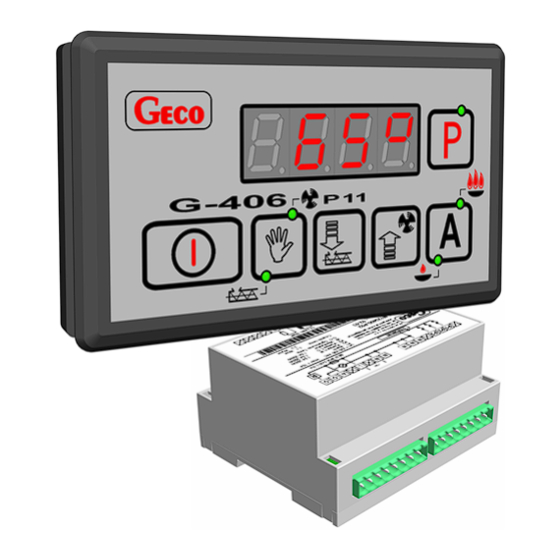
G-406-P11
TO CONTROL CENTRAL
HEATING BOILERS
FOR PELLETS
Program version: 10
You are politely requested for the familiarization with the manual prior to making the connection and
activating any of our machines. Should you have any doubts, please do not hesitate to contact our firm
between 8 a.m. and 16 p.m..
Note:
The most recent update release date is provided at the bottom of each following page. Please, always
use the most recent version of the manual, which can be obtained by mail free of charge after the
previous order.
Advertisement
Table of Contents

Related Manuals for Geco G-406-P11


Summary of Contents for Geco G-406-P11
- Page 1 USER MANUAL FOR THE AUTONOMOUS CONTROL UNIT (A.C.U.) G-406-P11 TO CONTROL CENTRAL HEATING BOILERS FOR PELLETS Program version: 10 You are politely requested for the familiarization with the manual prior to making the connection and activating any of our machines. Should you have any doubts, please do not hesitate to contact our firm between 8 a.m.
-
Page 2: Table Of Contents
TECHNICAL DATA ........................3 WIRING SYSTEM AND RULES OF CONNECTION ..............4 A.C.U. G-406-P11 OPERATION AND ADJUSTMENT METHODS ......... 4 ........................ 4 EMPERATURE MEASUREMENT ........ 4 XCEEDING THE ALLOWABLE TEMPERATURE OF THE FUEL IN THE FEEDING SCREW ............................ -
Page 3: General Characteristics
230 V, such as fan, fuel feeding unit, central heating system pump and flame ignition heater. If the unit is to act as the central heating system boiler controller, the G-406-P11 stabilizes the temperature of water and controls the process of fuel combustion in the boiler, preventing damping a fire. -
Page 4: Wiring System And Rules Of Connection
4. A.C.U. G-406-P11 OPERATION AND ADJUSTMENT METHODS Temperature measurement The controller measures the temperature within the range of 0 degree Centigrade to 100 degree Centigrade. -
Page 5: Power Failure
5. TEMPERATURE LIMITER (STB) The G-406-P11 controller has been equipped with additional mechanical protection, independent of automatics, called the safety temperature limiter (STB). Operation method:... -
Page 6: Stb Function Manual Reactivation
STB function manual reactivation When the STB temperature limiter has been triggers and fan deactivated, its operation must unconditionally be restored in order to ensure the proper functioning of the G-406-P11 controller. In order for the unit to be reactivated, proceed as follows: 1. -
Page 7: Manual Control
(heating and sustaining) and to enter the manual operation mode, involving the immediate stop of the operation of the fan, feeding screw and pump. PPUH „GECO” Sp. z o.o. Edition I RELEASE DATE 2006-10-06... -
Page 8: Flame Ignition
2. In this operation mode, the controller will additionally show whether the feeding screw and/or fan is activated through the activation of the corresponding control diodes arranged on the pushbutton. PPUH „GECO” Sp. z o.o. Edition I RELEASE DATE 2006-10-06... -
Page 9: Sustaining Mode Operation
Except for the AL4, the abandonment of the alarm modes is possible only when the pushbutton is pressed. PPUH „GECO” Sp. z o.o. Edition I RELEASE DATE 2006-10-06... -
Page 10: User Parameters Configuration
At the same time, the controller will enter the programming mode of the subsequent u1 parameter. Comments: • if the pushbutton is not pressed again, the changes will be discarded; PPUH „GECO” Sp. z o.o. Edition I RELEASE DATE 2006-10-06... -
Page 11: Time Of The Fuel Feeder Operation (U1)
The range of changes is between 1 and 10 which corresponds to 10% and 100%. The parameter in question may be modified in the same way as shown in item 6.1 and 6.2. PPUH „GECO” Sp. z o.o. Edition I... -
Page 12: Method Of Connecting The Equipment To The Controller
:0268 Date of Prod.: 09-02 4 - Additional line Temp. sensors Temperature delimiter Outlet water Flame Link temperature sensor sensor Figure 1. Diagram of equipment connection to the G-406-P11 controller PPUH „GECO” Sp. z o.o. Edition I RELEASE DATE 2006-10-06... -
Page 13: Troubleshooting Guide
• condition of the feeding connectors • the condition of feeding connectors screwing in • the correctness of the connection of the actuating module with the control panel • connect another data transfer tape. PPUH „GECO” Sp. z o.o. Edition I RELEASE DATE 2006-10-06... - Page 14 G-406-P11 SERVICE MANUAL PAGE 14 P.P.U.H. “Geco” Sp. z o. o. [Ltd.] Cholerzyn 376, 32-060 Liszki tel. 012 6369811, 6361290 fax. 012 6362002 http://www.geco.pl e-mail: geco@geco.pl PPUH „GECO” Sp. z o.o. Edition I RELEASE DATE 2006-10-06...
Need help?
Do you have a question about the G-406-P11 and is the answer not in the manual?
Questions and answers