Table of Contents
Advertisement
Quick Links
Advertisement
Table of Contents

Subscribe to Our Youtube Channel
Related Manuals for NKT Photonics Koheras BOOSTIK LC


Summary of Contents for NKT Photonics Koheras BOOSTIK LC
- Page 1 800-631-01 Koheras BOOSTIK LC Product Guide Revision 1.4 10-2023...
- Page 2 PRODUCT GUIDE This guide includes information for the following NKT Photonics products: Koheras BOOSTIK LC 2W 1550 nm 2W narrow linewidrh line card amplifier housed in a line card form factor Koheras BOOSTIK LC 200 mW 1550 nm 200 mW narrow linewidrh line card amplifier housed in a line card form factor...
-
Page 3: Guide Overview
Terminology The guide may refer to both the Koheras BOOSTIK LC as the laser amplifier or just simply module. The Koheras BOOSTIK LC is a module designed to be fitted to and as part of a complete laser system. - Page 4 • Chapter 4 “SDK Registers and Tabs” — An introduction to the registers and tabs of the Generic User Interface included with the NKT Photonics Software Development Kit. • Appendices — The guide includes multiple appendices including specifications, support contact details, connector pin assignments, error codes and a control software installation procedure.
- Page 5 Fixed the broken link in section “Errors” on page • Updated minor grammar and other link issues throughout. • Updated NKT Photonics website addresses. • Updated some of the pagination in chapter ““SDK Registers and Tabs” on page 49”. 2023-October Revision 1.4 •...
- Page 6 < 6 >...
-
Page 7: Table Of Contents
Front and rear panels......................18 Front panel ........................18 Rear panel ........................20 CONTROL GUI ......................21 Generic UI and NKT Photonics SDK ................21 Enabling emission ......................21 BOOSTIK LC labels ....................... 23 Installation ........................25 Passive cooling ........................25 Rear panel ........................ - Page 8 Connecting to the laser ....................33 Device Selector ......................33 Status panel ......................... 34 Status indicators ......................34 Error messages ......................35 System info ........................35 Measurements ....................... 35 Emission button ......................35 CONTROL settings ......................36 CONTROL menu ......................... 37 Key Updater tool ......................
- Page 9 Service and Support Information ................... 59 Servicing the laser........................ 59 Opening the module ....................... 59 WARRANTY VOID IF REMOVED label ................. 59 Support website ......................60 Electrical interface pinout ....................61 Fault troubleshooting ..................... 63 Contact support ......................63 Control Software......................65 Installing CONTROL ......................
- Page 10 < 10 >...
-
Page 11: Tables
TABLES Table 1: BOOSTIK LC variants and their characteristics ............18 Table 2: Status LEDs ........................22 Table 3: BOOSTIK LC Chassis labels ..................23 Table 4: CONTROL panels and menu..................31 Table 5: Device Monitor parameters................... 41 Table 6: Module overview fields....................46 Table 7: Generic user interface registers.................. - Page 12 < 12 >...
-
Page 13: Figures
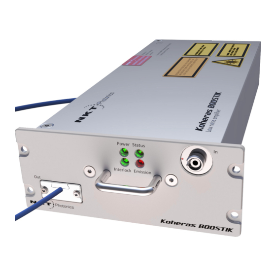
FIGURES Figure 1: BOOSTIK LC general view - front and rear panels............17 Figure 2: BOOSTIK LC front panel layout................... 19 Figure 3: Inserting a BOOSTIK LC into an ACOUSTIK shelf............19 Figure 4: BOOSTIK rear panel layout ..................20 Figure 5: Status LEDs......................... - Page 14 Figure 35: Stage one input monitor..................... 52 Figure 36: Pump temperature ..................... 53 Figure 37: Pump 1 current ......................53 Figure 38: Error and status tab ....................54 Figure 39: Graphing tab ......................55 Figure 40: Mechanical dimensions – front panel (without faceplate) .......... 58 Figure 41: Mechanical dimensions –...
-
Page 15: Procedures
PROCEDURES Procedure 1: Relocating panels ....................32 Procedure 2: Using the Key Updater tool .................. 38 Procedure 3: Using the Log Downloader ................... 39 Procedure 4: Installing CONTROL....................65 < 15 >... - Page 16 < 16 >...
-
Page 17: Description
Description The Koheras BOOSTIK LC is a compact fiber amplifier module for low-noise, narrow-linewidth Koheras seed lasers. The module is designed as a line card component of a complete laser system. The module inserts into a Koheras ACOUSTIK 16-slot rack shelf where it occupies two slots. -
Page 18: Variants
Front and rear panels Variants Three different BOOSTIK LC variants are available and mainly characterized by their output power and center wavelength. You can compare their characteristics in Table 1 below. Table 1 BOOSTIK LC variants and their characteristics Variant: 2 W@ 1550 nm 200 mW@1550 nm 200 mW@1064 nm Compatible Koheras seed laser(s) E15, X15,C5... -
Page 19: Figure 2 Boostik Lc Front Panel Layout
Front and rear panels For more information see “Status LEDs” on page Figure 2 BOOSTIK LC front panel layout Koheras ACOUSTIK faceplate 4 Output fiber and connector Status LEDs 5 Handle Input fiber connector (from BASIK) TBD type? Koheras ACOUSTIK faceplate A faceplate is mounted onto the front panel of the module casing and has four screw holes that align with the mounting holes of the ACOUSTIK slots. -
Page 20: Rear Panel
Front and rear panels Input fiber connector A threaded E2000 input connector. The connector is designed to received the seed optical signal from a BASIK module. Output fiber and connector Optical output fibers and connectors are specified in Table Handle Grip the handle firmly, when inserting and removing the BOOSTIK LC from a slot in the ACOUSTIK shelf. -
Page 21: Control Gui
CONTROL GUI You can manage a BOOSTIK LC laser amplifier and all other modules inserted into an ACOUSTIK shelf using NKT Photonics CONTROL graphical user interface (GUI) software installed on a PC. The PC is connected to an ACOUSTIK through either a USB or Ethernet connection. -
Page 22: Table 2 Status Leds
Status LEDs Status LEDs The rear panel houses four status LEDs that behave as described in Table The LEDs are located on the center top of the front panel as shown in Figure Figure 5 Status LEDs Interlock Power Status Emission Table 2 Status LEDs LED Name... -
Page 23: Boostik Lc Labels
Chassis labels Chassis labels BOOSTIK LC labels The Koheras BOOSTIK LC chassis includes multiple labels that indicate hazards, regulatory and manufacturing information. The labels are described in Table 3 and their location is shown in Figure Table 3 BOOSTIK LC Chassis labels... -
Page 24: Figure 6 Top Panel Label Locations
Chassis labels Figure 6 Top panel label locations WARRANTY VOID IF SEAL IS BROKEN OR REMOVED DESIGNATED FOR USE SOLELY AS A COMPONENT, WARNING - ISIBLE LASER RADIATION AND DOES NOT COMPLY WITH IEC 60825-1 OR AVOID EXPOSURE TO BEAM 21 CFR 1040.10 AS A COMPLETE LASER PRODUCT CLASS 4 LASER COMPONENT MAXIMUM OUTPUT POWER: 5W... -
Page 25: Installation
Installation Safety A Koheras BOOSTIK LC is a Class 4 laser and exposure to its emission ARNING is hazardous. Follow all regional laser safety regulations regarding installation, operation, and otherwise. Ensure to verify with your Laser Safety Officer (LSO) that the installation follows all applicable safety regulations and do no operate the laser until the officer approves it. -
Page 26: Left Side Panel Surface
Figure 9 shows a custom passive cooling block mounted on the left panel. The block is custom built and illustrated as an example only. NKT Photonics only supplies cooling fins included on the rear of an Koheras ACOUSTIK shelf. Figure 9 Custom passive cooling block mounted on the left panel... -
Page 27: Custom Installation Rules
Custom mounting using a custom mounting bracket (not included) attached to the side of the module as shown in Figure Figure 10 Example custom mount installation M6 bolt M6 bolt M6 bolt M6 bolt • Custom installation Allow for proper ventilation and cable access. rules •... -
Page 28: Fiber Tip Cleaning
Interlock Interlock The BOOSTIK LC includes a safety Interlock function. The function shuts down the emission immediately when a circuit loop connected to pins A3 and A4 is either opened or shorted to ground. When inserted into an ACOUSTIK shelf, the interlock circuit loop is connected through all installed modules and an external door switch circuit to protect the operating enclosure. -
Page 29: Signs Of Damage
If you do not obtain a good beam profile after polishing, the connector AUTION may be damaged. Return the laser to NKT Photonics for repair. Note that this type of repair is not covered by warranty. < 29 >... - Page 30 Polishing < 30 >...
-
Page 31: Control Gui
CONTROL GUI CONTROL GUI overview The CONTROL window includes multiple panels and a selection of menu drop down items in the upper left corner. Using the top left drop-down menu, you can add or remove the displayed panels and panels can be dragged within the main window or into separate windows. -
Page 32: Relocating Panels
CONTROL GUI overview Relocating panels You can drag the different panels of CONTROL to any location within the main interface or into a separate floating panel. Procedure 1 describes how to relocate a panel within the main window. Procedure 1 Relocating panels Action Left click and hold the top title bar of the panel. -
Page 33: Toggling Panels Visible
CONTROL GUI overview Toggling panels Use the Menu > Window drop down menu to check and uncheck panels to be visible displayed. A blue check mark indicates the panel is displayed. Figure 16 Toggling panel visibility Check the panels to display them To close a panel, click the X at the upper right corner of the panel. -
Page 34: Status Panel
Status panel Figure 18 Device selector panel ACOUSTIK rackmount smart chassis BASIK seed laser BOOSTIK LC selected Status panel The Status Panel provides status indicators, error messages, system information, emission control function and a settings menu. Figure 19 Status panel indicators Click Status indicators The panel displays the following indicators:... -
Page 35: Error Messages
Status panel Interlock Indicates the state of the safety interlock circuit. • ON Green – The interlock loop back circuit is closed i.e. connected. • ON Red – The interlock loop back circuit is shorted to earth or open. For example, a connected door switch is open. -
Page 36: Control Settings
Status panel CONTROL settings CONTROL settings are accessible by clicking the gear icon in the upper right corner of the Status panel. Clicking the gear icon displays a drop-down menu of setting items as shown in Figure Figure 20 CONTROL settings Click the gear icon to access the menu Setting Item... -
Page 37: Control Menu
CONTROL menu View Check the Module info box to display the laser serial number and firmware release number within the status panel. Check the Measurements box to display the system temperature in the status panel. In the User text: field, input an alphanumeric text string for the module. The string is displayed next to the module icon in the Device Selector. -
Page 38: Key Updater Tool
NKT Photonics support personnel. Log downloader If your laser requires support from NKT Photonics, our support engineers may request that you send the log files collected by the laser. You can use the log downloader tool to save the laser log files to your CONTROL PC. -
Page 39: Procedure 3 Using The Log Downloader
CONTROL automatically downloads log files from the modules of any connected devices. The log files are stored in a local database on the CONTROL PC. However, certain modules, including the Koheras BOOSTIK LC main board do not support automatic download of log files. For these modules. you can use the Log Downloader tool to put the device into dedicated log download mode by enabling a collect log function. -
Page 40: Extensions Overview
Extensions overview You can use the Extensions Overview tool to view the installed extensions (plugins) that are included with CONTROL. The extensions are found in the following folder: C:\Program Files (x86)\NKT Photonics\NKTP CONTROL\Plugins < 40 >... -
Page 41: Device Monitor
CONTROL menu To view the extensions, open the Tools menu and click on Extensions Overview. The Extensions Overview window is launched as shown in Figure Figure 24 Extensions Overview To show a short description of the release notes as seen in Figure 24, hover the mouse pointer over the Release notes text... -
Page 42: Application Log
CONTROL menu Parameter Description Status bits The actual status bits read from the connected module. Error code The actual error code read from the connected module. Access Protected/Locked status of the module. FW Ver. The device module’s firmware release date. Module Serial The serial number of the device module PCB Serial... -
Page 43: Figure 25 Serial Monitor
CONTROL menu COM port open and close times and also general status information. You can clear, save and print the log data using the buttons in the upper left corner. Figure 25 Serial monitor Clear the log Save the log to file Print the log The panel is enabled by placing a check mark on the Window drop-down menu next to the Application Log item. -
Page 44: Power Mode
Control panel Control panel Power mode When set to Power mode within the Control Panel you can view both the measured input and output power, plus you can set the setpoint level of the output power. The laser amplifier measures the optical output power and uses the measurement to constantly adjust the level to the setpoint. -
Page 45: Module Overview
Module overview Input The Input field displays the optical power in milliwatts measured at the In (input) fiber port. Output The Output field displays the optical power in milliwatts measured at the Out (output) fiber port. This is the laser output aperture power and you can display the power level in either mW or dBm units by clicking the drop-down menu arrow. -
Page 46: Toggling And Sorting The Overview Fields
Red ON - Interlock circuit open or key switch off. Error code Error code for an existing module fault - contact NKT Photonics support of the error persists. Module Serial Factory serial number of the module. FW. Ver. Firmware currently executing on the module. -
Page 47: Figure 29 Module Overview Field Selection
Module overview To remove a field from the overview, click once on the any of the fields (except for Module) to uncheck it. Clicking once on an unchecked field, adds it back to the overview. Figure 29 Module overview field selection Click any field to remove it;... - Page 48 Module overview < 48 >...
-
Page 49: Sdk Registers And Tabs
SDK Registers and Tabs NKT Photonics’ Software Development Kit (SDK) allows access to registers controlling the module’s operating parameters using its Generic User Interface (Generic UI). For general operation it is recommended to use CONTROL. This section’s purpose is to help introduce how to use the Generic User Interface to set some of the laser’s operating parameters. -
Page 50: Output Power Setpoint
Read/write registers Figure 30 Read/write registers under the Control tab Readings Output power Input the setpoint power level of the optical output in mW or dBm. For setting setpoint the power using mW units, use register 22, and for using dBm units, used register A0. -
Page 51: Setup Bits
Read/write registers fault is raised with error code 60 displayed – see “Errors and status indicators” on page Figure 32 Enabling emission Setup bits Register 31 Setup bits configures the laser amplifier to operate in either current or power mode. Set as follows; •... -
Page 52: Stage One Input Monitor
Readings Readings To monitor the BOOSTIK LC, click on the Readings tab in the right side of the Generic UI window to view the contents of read-only registers. For read-only registers not described in this document, refer to the SDK instruction manual included with the SDK installation. -
Page 53: Pump Temperature
Readings Pump temperature The hard-coded pump temperature of the BOOSTIK LC is displayed in Readings register 13. When operating, the module is designed to maintain its pump temperature at this value. Figure 36 Pump temperature Heat sink Register 1C displays the temperature measurement from a sensor within the temperature module near its rear passive cooling surface. -
Page 54: Status Indicators
Status indicators The status indicators is lit green if the condition in the text is true. Errors If an error code is listed and cannot be cleared contact NKT Photonics support, “Support contact details” on page Error codes are listed in... -
Page 55: Figure 39 Graphing Tab
Graphing Graphing As shown in Figure 39, you can graph the values of selected parameters by clicking on the Graph tab and selecting the parameters you want to graph. To use the graphing function: Select the parameters to graph from the drop-down menu at the left/right y- axis and bottom x-axis of the graph. - Page 56 Graphing < 56 >...
-
Page 57: Specifications
Specifications Table 8 Optical specifications Variant: 2W @ 1550 200mW @ 1550 200 mW @ 1064 Mode of operation Continuous wave - inherently single frequency Output power 2.0 W 200 mW 200 mW Wavelength range 1545-1565 nm 1545-1565 nm 1060-1075 nm Output fiber PM1550 or SMF28 PM1150 PM980... -
Page 58: Figure 40 Mechanical Dimensions - Front Panel (Without Faceplate)
Figure 40 Mechanical dimensions – front panel (without faceplate) Figure 41 Mechanical dimensions – side panel Figure 42 Mechanical dimensions – rear panel < 58 >... -
Page 59: Service And Support Information
Service and Support Information Servicing the laser The laser amplifier has no user serviceable components. In case of malfunction, contact NKT Photonics using the support channels in section “Support contact details” on page Do not open the laser amplifier module. The module is equipped with... -
Page 60: Support Website
Support contact details Support contact details If you need help or have questions regarding your Koheras BOOSTIK LC laser or its accessories, contact NKT Photonics through our support website below: Support website 1. Go to: https://www.nktphotonics.com/support 2. Scroll down and click or press: 3. -
Page 61: C Electrical Interface Pinout
Electrical interface pinout Figure 44 C/3 electrical interface pins 10 9 30 pin DIN41612 male C/3 type Table 13 C/3 electrical interface pin descriptions Pin # Signal Description Module OK Low: module enable low OR module power low High: module power high RS485- Negative/inverted RS485 differential data signal Interlock loop+... - Page 62 < 62 >...
-
Page 63: D Fault Troubleshooting
Contact support If you require further support to resolve the error, contact NKT Photonics support – see “Support contact details” on page 60. Ensure to include error codes and collected log files –... - Page 64 Code Name Description Solution (perform in sequence) Stage 2 input Internal optical power low. 1. Contact support with error code and log files. power Maximum output Maximum output power 1. Contact support with error code and log files. power exceeded exceeded.
-
Page 65: Control Software
Control Software Installing CONTROL Download the software from: https://www.nktphotonics.com/support Follow the steps in Procedure Procedure 4 Installing CONTROL Action On the PC, launch the installer package and then click the Installer Run button. The installation wizard appears. Click Next to continue. Accept to use the default installation directory or select another directory by clicking the Browse button. - Page 66 Installing CONTROL Action Uncheck the components you do not require. By default, all components are installed. Click Next to continue. Read the End-User License Agreement, and check “I accept the license.” box. Not checking the box ends the installation wizard. Click Next to continue.
- Page 67 Installing CONTROL Action Check the box to create a desktop shortcut to access Control. Click Next to continue Check the ‘Run the Silicon Labs CP10x driver installation’ box and click Next. Note: USB connectivity fails if you do not install the driver. Click Install to install NKTP CONTROL software on your Click Cancel if you want to abort the installation.
- Page 68 Installing CONTROL Action The wizard displays a progress meter for the installation. Note: a normal install should only take a few seconds. Click Next to install the UART drivers for the PC USB port. The drivers are installed. Note: Depending on your computer this occurs so fast you may not see this.
- Page 69 Installing CONTROL Action The Silicon Labs drivers is installed successfully. Click Finish to end the driver installation. CONTROL is now installed. Check the Run box to launch CONTROL when the Finish button is clicked. Click Finish to end the installation wizard. <...
- Page 70 Installing CONTROL < 70 >...
- Page 72 Blokken 84, Birkerød-3460 Denmark The information in this publication is subject to change without notice. All company and product names mentioned within are either trademarks or registered trademarks of NKT Photonics. Specifications are listed as metric units. Imperial units listed are conversions.
Need help?
Do you have a question about the Koheras BOOSTIK LC and is the answer not in the manual?
Questions and answers