Table of Contents
Advertisement
Quick Links
Advertisement
Table of Contents

Subscribe to Our Youtube Channel
Related Manuals for NKT Photonics Koheras BOOSTIK LC


Summary of Contents for NKT Photonics Koheras BOOSTIK LC
- Page 1 Koheras BOOSTIK LC Narrow linewidth laser amplifier PRODUCT GUIDE Item 800-631-01...
- Page 2 200 mW narrow linewidrh line card amplifier housed in a line card form factor Koheras BOOSTIK LC 200 mW 1064 nm 200 mW narrow linewidrh line card amplifier housed in a line card form factor Koheras BOOSTIK LC Product Description Revision 1.1 10-2021 W-10456...
-
Page 3: Guide Overview
Terminology The guide may refer to both the Koheras BOOSTIK LC as the laser amplifier or just simply module. The Koheras BOOSTIK LC is a module designed to be fitted to and as part of a complete laser system. - Page 4 Added information Lasers are highly dangerous devices that can cause serious injury and property damage. This guide use the following symbols to either highlight important safety and Safety Notices information or provide further information in relation to a specific topic. Note: Highlights additional information related to the associated topic and/or pro- vides links or the name of the NKTP guides describing the additional information.
-
Page 5: Table Of Contents
Front and rear panels ................16 Front panel ..................16 Rear panel ..................18 CONTROL GUI ................. 19 Generic UI and NKT Photonics SDK ..........19 Enabling emission ................19 BOOSTIK LC labels ................21 2 Installation ..................... 23 Safety ..................... 23 Passive cooling .................. - Page 6 CONTROL GUI overview ............... 29 Relocating panels ................30 Connecting to the laser ..............31 Device Selector .................. 31 Status panel .................... 32 Status indicators ................32 Error messages ................. 33 System info ..................33 Measurements ................... 33 Emission button ................. 33 CONTROL settings ................
- Page 7 Status indicators ................50 Errors ....................50 Graphing ....................50 A Specifications ....................53 B Service and Support Information ..............55 Servicing the laser .................. 55 Opening the module ................55 WARRANTY VOID IF REMOVED label ..........55 Support website ................. 56 C Electrical interface pinout ................
-
Page 9: Tables
TABLES Table 1: BOOSTIK LC variants and their characteristics ......... 16 Table 2: Status LEDs..................20 Table 3: BOOSTIK LC Chassis labels ............. 21 Table 4: CONTROL panels and menu ............. 29 Table 5: Device Monitor parameters ..............39 Table 6: Module overview fields ............... 43 Table 7: Generic user interface registers ............ -
Page 11: Figures
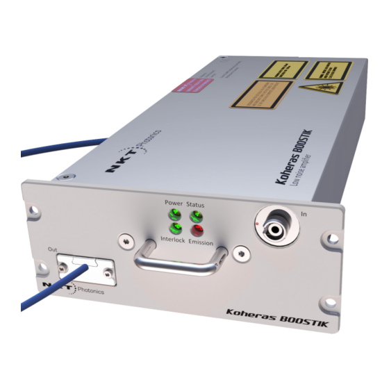
FIGURES Figure 1: BOOSTIK LC general view - front and rear panels ......15 Figure 2: BOOSTIK LC front panel layout ............17 Figure 3: Inserting a BOOSTIK LC into an ACOUSTIK shelf ......17 Figure 4: BASIK rear panel layout ..............18 Figure 5: Status LEDs .................. - Page 12 Figure 29: Module overview field selection ............44 Figure 30: Read/write registers under the Control tab ........46 Figure 31: Setting the output power setpoint ........... 46 Figure 32: Enabling emission ................47 Figure 33: Setting the setup bits ..............47 Figure 34: Read-only (monitor) registers under the Readings tab ....
-
Page 13: Procedures
PROCEDURES Procedure 1: Relocating panels ..............30 Procedure 2: Using the Key Updater tool ............36 Procedure 3: Using the Log Downloader............37 Procedure 4: Installing CONTROL ..............61... -
Page 15: Description
Description The Koheras BOOSTIK LC is a compact fiber amplifier module for low-noise, narrow- linewidth Koheras seed lasers. The module is designed as a line card component of a complete laser system. The module inserts into a Koheras ACOUSTIK 16-slot rack shelf where it occupies two slots. -
Page 16: Variants
Front and rear panels Variants Three different BOOSTIK LC variants are available and mainly characterized by their output power and center wavelength. Their specific characteristics can be seen in Table 1 below. Table 1 BOOSTIK LC variants and their characteristics 200 mW @ 1550 nm 200 mW @ 1064 nm Variant: 2 W@ 1550 nm... -
Page 17: Figure 2 Boostik Lc Front Panel Layout
Front and rear panels Figure 2 BOOSTIK LC front panel layout Koheras ACOUSTIK faceplate 4 Output fiber and connector Status LEDs 5 Handle Input fiber connector (from BASIK) TBD type? Koheras ACOUSTIK faceplate The faceplate is mounted onto the front panel of the module casing and has four screw holes that align with the mounting holes of the ACOUSTIK slots. -
Page 18: Rear Panel
Front and rear panels Output fiber and connector The optical output aperture fibers and connectors are specified in Table Handle Grip the handle firmly, when inserting and removing the BOOSTIK LC from a slot in the ACOUSTIK shelf. Rear panel The rear panel, shown in Figure 4, it includes the main electrical interface, alignment... -
Page 19: Control Gui
You can manage the BOOSTIK LC laser amplifier and all other modules inserted into an ACOUSTIK shelf using NKT Photonics CONTROL graphical user interface (GUI) software installed on a PC. The PC is connected to the ACOUSTIK through either an USB or Ethernet connection. -
Page 20: Table 2 Status Leds
The interlock status is Not OK – the door circuit is open or not energized. Note: the laser until you are familiar with the controls and have taken O NOT OPERATE all precautions necessary as described in the Koheras BOOSTIK LC-series Laser Safety, Handling and Regulatory Information. -
Page 21: Boostik Lc Labels
Front and rear panels Chassis labels BOOSTIK LC labels The Koheras BOOSTIK LC chassis includes multiple labels that indicate hazards, regulatory and manufacturing information. The labels are described in Table 3 their location is shown in Figure Table 3 BOOSTIK LC Chassis labels... -
Page 22: Figure 6 Top Panel Label Locations
Front and rear panels Figure 6 Top panel label locations WARRANTY VOID IF SEAL IS BROKEN OR REMOVED DESIGNATED FOR USE SOLELY AS A COMPONENT, WARNING - ISIBLE LASER RADIATION AND DOES NOT COMPLY WITH IEC 60825-1 OR AVOID EXPOSURE TO BEAM 21 CFR 1040.10 AS A COMPLETE LASER PRODUCT CLASS 4 LASER COMPONENT MAXIMUM OUTPUT POWER: 5W... -
Page 23: Installation
Safety Warning: A Koheras BOOSTIK LC is a Class 4 laser and exposure to its emission is hazardous. Follow all regional laser safety regulations regarding installation, opera- tion, and otherwise. Ensure to verify with your Laser Safety Officer (LSO) that the in- stallation follows all applicable safety regulations and do no operate the laser until the officer approves it. -
Page 24: Left Side Panel Surface
Figure 9 shows a custom passive cooling block mounted on the left panel. The block is custom built and shown as an example only. NKT Photonics only supplies cooling fins included on the rear of an Koheras ACOUSTIK shelf. Figure 9 Custom passive cooling block mounted on the left panel... -
Page 25: Custom Installation Rules
Interlock Figure 10 Example custom mount installation M6 x M6 x bolt ?bolt M6 x M6 x ?bolt bolt • Custom installation Allow for proper ventilation and cable access. rules • Do not store or place anything on the top panel of the amplifier. •... -
Page 26: Fiber Tip Cleaning
Fiber tip cleaning When inserted into an ACOUSTIK shelf, the interlock circuit loop is connected to all installed modules and an external door switch circuit to protect the operating enclosure. For more information regarding the Interlock and how to connect a door safety switch, refer to the Koheras ACOUSTIK Product Guide. -
Page 27: Damaged Facet
3. Continue this "quick polish, check beam" process until a well-formed beam is obtained. Caution: If you do not obtain a good beam profile after polishing, the connector may be damaged. Return the laser to NKT Photonics for repair. Note that this type of repair is not covered by warranty. - Page 28 Polishing...
-
Page 29: Control Gui
CONTROL GUI CONTROL GUI overview The CONTROL window includes multiple panels and a selection of menu drop down items in the upper left corner. Using the top left drop-down menu, you can add or remove the displayed panels and panels can be dragged within the main window or into separate windows. -
Page 30: Relocating Panels
CONTROL GUI overview Relocating panels The panels displayed by GUI can be dragged to other positions within the main interface or apart as separated floating panels. Procedure 1 describes how to move a panel: Procedure 1 Relocating panels Action Left click hold the top title bar of any panel. While holding the left mouse button down, drag the panel to another position in the main window. -
Page 31: Connecting To The Laser
CONTROL GUI overview Figure 16 Panels dragged outside the main window Check the panels names to display them Note: Clicking the X in the upper right corner of any panel also closes it. Connecting to the When CONTROL launches, the Welcome panel is displayed as in Figure 17. -
Page 32: Status Panel
Status panel Figure 18 Device selector panel ACOUSTIK rackmount smart chassis BASIK seed laser BOOSTIK LC selected Status panel The Status Panel provides status indicators, error messages, system information, emission control function and a settings menu. Figure 19 Status panel indicators Click Status indicators The panel displays the following indicators:... -
Page 33: Error Messages
Status panel • ON Red – The interlock loop back circuit is shorted to earth or open. For example, a connected door switch is open. Status Indicates the operational state of the laser. • ON Red – An fault in the modules operation has occurred producing an error message in the status panel. -
Page 34: Figure 20 Control Settings
Status panel Figure 20 CONTROL settings Click the gear icon to access the menu Setting Item Function Power/current When selected, the control panel allows you Power/current mode on mode to set the amplifier to operate in either page 34 power or current mode. View Panel with check boxes to enable displaying View on page 35 the module Information and/or the system... -
Page 35: Control Menu
CONTROL menu View Check the Module info box to display the laser serial number and firmware release number within the status panel. Check the Measurements box to display the system temperature in the status panel. In the User text: field, input an alphanumeric text string for the module. The string is displayed next to the module icon in the device selector. -
Page 36: Key Updater Tool
NKT Photonics support personnel. Log downloader If your laser requires support from NKT Photonics, our support engineers may request that you send the log files collected by the laser. You can use the log downloader tool to save the laser log files to your CONTROL PC. -
Page 37: Procedure 3 Using The Log Downloader
CONTROL menu will be disabled Note: Right clicking any device in the “Device monitor”, also displays log download functions. To download log files use the Log Downloader as described in Procedure Procedure 3 Using the Log Downloader Action Open the Tools menu and click on Log Download to start the Log Downloader tool. -
Page 38: Extensions Overview
CONTROL. The extensions are found in the following folder: C:\Program Files (x86)\NKT Photonics\NKTP CONTROL\Plugins To view the extensions, open the Tools menu and click on Extensions Overview. The Extensions Overview window will be launched as shown in... -
Page 39: Device Monitor
CONTROL menu Device monitor The device monitor provides a real-time display of communication port parameters and any connected device modules. The parameter values displayed are continuously updated and can be used to help debug issues with connected devices. The parameters are listed and described in Table Table 5 Device Monitor parameters... -
Page 40: Application Log
CONTROL menu Parameter Description Total number of received telegrams with CRC failures Total number of communication errors with framing or protocol errors. Hover over the icon to list more details. Busy Total number of busy responses from the module. Busy responses occur when the module receives a message but cannot process it due to its current work load. -
Page 41: Power Mode
CONTROL menu Control panel Power mode When set to Power mode within the Control Panel you can view both the measured input and output power, plus you can set the setpoint level of the output power. The laser amplifier measures the optical output power and uses the measurement to constantly adjust the level to the setpoint. -
Page 42: Module Overview
Module overview Output The Output field displays the optical power in milliwatts measured at the Out (output) fiber port. This is the laser output aperture power and you can display the power level in either mW or dBm units by clicking the drop-down menu arrow. Figure 27 Current mode –... -
Page 43: Toggling And Sorting The Overview Fields
Module overview The following information is available from each of the available fields: Table 6 Module overview fields Column heading Description Module Chassis slot number Reference WL Base wavelength of the module in nm Actual WL Output wavelength of the module in nm WL offset Setpoint Wavelength offset set with CONTROL in pm Actual WL offset... -
Page 44: Figure 29 Module Overview Field Selection
Module overview Figure 29 Module overview field selection Click any field to remove it; click it again to add it back... -
Page 45: Sdk Registers And Tabs
This chapter introduces the Generic UI and its registers. For a full description of the SDK, registers and using the Generic User Interface, refer to the NKT Photonics document: SDK Instruction Manual. The manual is installed when the SDK installer is run. -
Page 46: Output Power Setpoint
Read/write registers Figure 30 Read/write registers under the Control tab Readings Output power Input the optical output setpoint power level in mW or dBm. For setting the power using mW units, use register 22, and for using dBm units, used register A0. setpoint Figure 31 Setting the output power setpoint Emission... -
Page 47: Setup Bits
Read/write registers Figure 32 Enabling emission Setup bits Register 31 Setup bits configures the laser amplifier to operate in either current or power mode. Set as follows; • 0000 – Power mode • 0001 – Current mode Figure 33 Setting the setup bits... -
Page 48: Stage One Input Monitor
Read/write registers Readings To monitor the BOOSTIK LC, click on the Readings tab in the right side half of the Generic UI window to view the contents of read-only registers. For read-only registers not described in this document, refer to the SDK instruction manual included with the SDK installation. -
Page 49: Heat Sink Temperature
Read/write registers Figure 36 Pump temperature Heat sink Register 1C displays the a temperature measurement from a sensor within the module near its rear passive cooling surface. temperature Figure 37 Pump 1 current... -
Page 50: Errors And Status Indicators
The status indicators will be lit green if the condition in the text is true. Errors If an error code is listed and cannot be cleared contact NKT Photonics support, see “Support contact details” on page Error codes are listed in... -
Page 51: Figure 39 Graphing Tab
Graphing Figure 39 Graphing tab Y-axis settings X-axis setting... - Page 52 Graphing...
-
Page 53: A Specifications
Specifications Table 8 Optical specifications Variant 2W @ 1550 200mW @ 1550 200 mW @ 1064 Mode of operation Continuous wave - inherently single frequency Output power 2.0 W 200 mW 200 mW Wavelength range 1545-1565 nm 1545-1565 nm 1060-1075 nm Output fiber PM1550 or SMF28 PM1150... -
Page 54: Figure 40 Mechanical Dimensions - Front Panel (Without Faceplate)
Figure 40 Mechanical dimensions – front panel (without faceplate) Figure 41 Mechanical dimensions – side panel Figure 42 Mechanical dimensions – rear panel... -
Page 55: B Service And Support Information
Service and Support Information Servicing the laser The laser amplifier has no user serviceable components. In case of malfunction, contact NKT Photonics using the support channels in section “Support contact details” on page Caution: Do not open the laser amplifier module. The module is equipped with war-... -
Page 56: Support Website 1
Servicing the laser Support contact details If you need help or have questions regarding your Koheras BOOSTIK LC laser or its accessories, contact NKT Photonics through our support website below: Support website 1. Go to: https://www.nktphotonics.com/lasers-fibers/support/technical-support-and- customer-service/ Scroll down and click or press:... -
Page 57: C Electrical Interface Pinout
Electrical interface pinout Figure 44 C/3 electrical interface pins 10 9 30 pin DIN41612 male C/3 type Table 13 C/3 electrical interface pin descriptions Pin # Signal Description Module OK Low: module enable low OR module power low High: module power high RS485- Negative/inverted RS485 differential data signal Interlock loop+... -
Page 59: D Fault Troubleshooting
Contact support If you require further support to resolve the error, contact NKT Photonics support – “Support contact details” on page 56. Ensure to include error codes and collected log files –... - Page 60 Code Name Description Solution (perform in sequence) Maximum output Maximum output power Contact support with error code and log files. power exceeded exceeded. Stage 1 current high Stage 1 current too high Contact support with error code and log files. Stage 2 current high Stage 2 current too high Contact support with error code and log files.
-
Page 61: E Control Installation
CONTROL installation Installing CONTROL Download the software from: https://www.nktphotonics.com/lasers-fibers/support/software-drivers/ Follow the steps in Procedure Procedure 4 Installing CONTROL Action On the PC, launch the installer package and then click the Installer Run button. The installation wizard appears. Click Next to continue. - Page 62 Action Accept to use the default installation directory or select another directory by clicking the Browse button. Click Next to continue. Uncheck the components you do not require. By default, all components will be installed. Click Next to continue. Read the End-User License Agreement, and select: “I accept the license.”.
- Page 63 Action The wizard will create a start menu folder with program short-cuts. Use the default name or enter a new name for the folder. Click Next to continue. Check the box to create a desktop shortcut to access Control. Click Next to continue Check the Silicon Labs driver installation (recommended) and click Next.
- Page 64 Action Click Install to install NKTP CONTROL software on your PC. Click Cancel if you want to abort the installation.. The wizard displays a progress meter for the installation. Note: a normal install should only take a few seconds. Click Next to install the UART drivers for the PC USB port. Read the End-User License Agreement, and select “I accept this agreement”.
- Page 65 Action The drivers will be installed. The Silicon Labs drivers is installed successfully. Click Finish to end the installation wizard. CONTROL is now installed. Check the Run box to launch CONTROL when the Finish button is clicked. Click Finish.
- Page 68 Koheras BOOSTIK LC Product Description Revision 1.1 10-2021 W-10456...
Need help?
Do you have a question about the Koheras BOOSTIK LC and is the answer not in the manual?
Questions and answers