Charge Amps Amp Guard Installation Manual
Hide thumbs
Also See for Amp Guard:
- Quickmanual installation (57 pages) ,
- Quick manual (56 pages) ,
- Installation manual (26 pages)
Table of Contents
Advertisement
Quick Links
Advertisement
Table of Contents

Related Manuals for Charge Amps Amp Guard


Summary of Contents for Charge Amps Amp Guard
- Page 1 Charge Amps Amp Guard Installation English Manual www.chargeamps.com...
-
Page 2: Table Of Contents
Connect the terminal block for voltage measurement Mount and connect the power supply Install internet connection 5.5.1 Wi-Fi connection 5.5.2 LAN connection Configuration Create a Charge Amps Partner account Connect to internet via Charge Amps Amp Guard Wi-Fi access point... - Page 3 Configuration in the Local management interface 6.4.1 Facility Wi-Fi network configuration 6.4.2 Electrical settings Verify Charge Amps Amp Guard configuration Configure Charge Amps Load balancing functionality Cloud connectivity Maintenance and operation Reboot Charge Amps Amp Guard Reset Charge Amps Amp Guard...
- Page 4 Failure to follow and carry out the directions, instructions and safety precautions in this Installation Manual will invalidate the warranty and subsequently release Charge Amps AB from any and all liability claims in connection with any injuries/damage or incidents that result from said failure either directly or indirectly.
-
Page 5: Safety
• Do not immerse the product in water, subject it to physical abuse or insert foreign objects in any part of the product. • Never attempt to disassemble the product in any way. • Charge Amps Amp Guard is a power monitor. Only use the product for its intended use... -
Page 6: Technical Data
230 VAC (+/-15%) 50 Hz power supply Installation DIN rail mounting in a cabinet: 1M for Charge Amps Amp Guard 1M for the power supply Dimensions (W x D x H) Charge Amps Amp Guard: 17.5 x 73* x 100 mm Power supply: 17.5 x 58 x 90 mm... - Page 7 English Climatic conditions Operating temperature: -35°C to +55°C Relative humidity: 0 - 90% Altitude: 0 - 2000 m Pollution Degree: 2 Ingress protection: IP2X Indoor meter: Yes Energy consumption 1.3 kWh/1000h Function characteristics according to IEC 61557-12 Function symbols Function Measuring range Other performance...
-
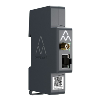
Page 8: Product Overview
English 3 Product overview Charge Amps Amp Guard Wi-Fi antenna connector Reset button (at the top of LAN/RJ45 port Charge Amps logo) Serial number & PIN code Status indicators information... -
Page 9: Package Contents
Included in the package: • Monitoring module with current clamps • Charge Amps Amp Guard • 12 VDC power supply for powering Charge Amps Amp Guard • Wi-Fi antenna • 12 V power cable • Terminal block for voltage measurement Additional contents: •... -
Page 10: Status Indicators
English 3.2 Status indicators Charge Amps logotype: • Lights On – Power On • Lights Off – Power Off Communication status: • Green light – Connected to cloud • Blue light – Connected to network • No light – No network connection Voltage measurement status: •... -
Page 11: Before Installation
In order to transmit data to the load balancing function which communicates with the charging station(s), Charge Amps Amp Guard must be connected to the internet. A connection via either Wi-Fi or LAN is possible for Charge Amps Amp Guard. 4.2.1 Wi-Fi connection... -
Page 12: Lan Connection
Charge Amps Amp Guard: • A network cable, at least Cat6. • Normally, no firewall changes are necessary. • The network needs to have DHCP enabled to ensure an IP address is automatically assigned to the Charge Amps Amp Guard. -
Page 13: Installation
English 5 Installation To monitor all power usage, install Charge Amps Amp Guard directly downstream the building’s main circuit breaker panel. N.B: For single phase installations, L2 and L3 shall not be used. 5.1 Mount Charge Amps Amp Guard Before starting the mounting of Charge Amps Amp Guard, remember that an additional slot will be needed on the DIN-rail for mounting of the power supply. -
Page 14: Connect The Current Sensors
English 5.2 Connect the current sensors Charge Amps Amp Guard comes with three current sensors, one for each phase. 1. Clamp the current sensor around the incoming phase. The current sensors must be: • Connected to the correct phase. • Properly positioned around the main power cables. - Page 15 English 2. Connect the sensor cartridge to the top of the Charge Amps Amp Guard. N.B: To secure proper contact, hold a hand under the Charge Amps Amp Guard when connecting the sensor cartridge.
-
Page 16: Connect The Terminal Block For Voltage Measurement
1. Turn the power off at the main circuit breaker panel. 2. Connect the terminal block to the bottom of the Charge Amps Amp Guard. 3. Connect phases and neutral to the supplied terminal block... - Page 17 English • Wiring diagram - installation with power-generating equipment: connect all phases to the terminal block for voltage measurement. • Wiring diagram - installation without power-generating equipment: connect one of the phases to the terminal block for voltage measurement.
- Page 18 English • Wiring diagram - IT network* with power generating equipment: connect all phases to the terminal block for voltage measurement. • Wiring diagram - IT network* without power generating equipment: connect L1 and L2 to the terminal block for voltage measurement.
-
Page 19: Mount And Connect The Power Supply
The power supply is pre-configured to supply 12 V to Charge Amps Amp Guard. If needed, the voltage level can be adjusted by using the adjustment screw on the front of the power supply. 1. Connect the power supply to the mains and insert the supplied 12V power cable to the power supply according to the picture below. - Page 20 English 2. Mount the power supply onto the DIN-rail. 3. Connect the 12V power cable to the sensor cartridge. IMPORTANT! Be careful not to overpress the 12V power cable when connecting it to the sensor cartridge! 4. Turn the power on at the main circuit breaker panel.
-
Page 21: Install Internet Connection
1. Mount the Wi-Fi antenna, it shall point downwards so it doesn’t block the reset button on the top of the Charge Amps logo. N.B: Only rotate the nut, not thw Wi-Fi antenna itself and be careful not to tighten the nut too tight. -
Page 22: Configuration
• The serial number for Charge Amps Amp Guard (can be found on the front label or the Quick Guide). • The PIN code for Charge Amps Amp Guard (an 8-digit code that can be found on the front label or the Quick Guide). - Page 23 6.2 Connect to internet via Charge Amps Amp Guard Wi-Fi access point Before configuring the load balancing functionality in Charge Amps Cloud, Charge Amps Amp Guard needs to be connected to the internet. Once the power is switched on, Charge Amps Amp Guard will provide a Wi-Fi access point which is available for 10 minutes.
-
Page 24: Connect To Internet Via Lan
English 6.3 Connect to internet via LAN 1. Make sure Charge Amps Amp Guard is connected to the local network via an ethernet cable in the LAN/RJ45 port. 2. Log in to the facility router to find the IP adress assigned to Charge Amps Amp Guard). -
Page 25: Electrical Settings
) lights up green. This should take about a minute. 6.4.2 Electrical settings To function properly, the electrical settings for Charge Amps Amp Guard must be configured in the Local management interface. Information about main fuses and network type must be set. -
Page 26: Verify Charge Amps Amp Guard Configuration
After configuration, the installation, configuration and performance of Charge Amps Amp Guard needs to be verified: 1. Make sure that the status indicators on the Charge Amps Amp Guard indicate proper operation: • The communication indicator ( ) shall light up green. -
Page 27: Cloud Connectivity
Please download our app for complete control, to adjust settings and enable smart charging and scheduling. Charge Amps Cloud Please create an account in the Charge Amps Cloud to configure, control and manage your charger via our web interface. Partner Portal User Portal https://my.charge.space/... -
Page 28: Maintenance And Operation
See www.chargeamps.com/support. In the Local management interface, there is a “System” tab, where the Charge Amps Amp Guard can be rebooted or restored to factory settings if needed: 1. Log in to the Local management interface (depending on your internet connection, see chapter 6.2 or 6.3 for details on how... -
Page 29: Reset Charge Amps Amp Guard
Charge Amps Amp Guard can be restarted using the reset button. Data stored in the Charge Amps Cloud will not be affected. 1. Gently press the reset button at the top of the Charge Amps logo. 2. When the reset has been initiated, all lights will turn off for a... -
Page 30: Product Support And Service
English 9 Product support and service If you have any questions or problems with the product, support is always available. To find answers to your questions most quickly: Read through the Installation Manual to check whether your questions are answered here. If your question is not answered, please: 1. - Page 31 Charge Amps AB (publ) Frösundaleden 2B, 8th floor SE–169 75 Solna, Sweden Charge Amps UK Ltd 3 More London Riverside, 4th Floor London SE1 2AQ, United Kingdom Doc. no: 130820 © Charge Amps AB Rev: 02 All rights reserved...
Need help?
Do you have a question about the Amp Guard and is the answer not in the manual?
Questions and answers