Advertisement
Quick Links
No: 341098 – 10/14
Catalog Numbers: WDT301, WDT321
Country of Origin: Made in China
SPECIFICATIONS
Voltages: ............................................................................................. 120/277 VAC, 50/60 Hz
Load Limits for relay 1:
Load Limits for relay 2:
Time Delay Adjustment .................................................................................... 5 to 30 minutes
Walk-Through Mode .........................................................3 minutes if no activity after 30 sec.
WDT301
WDT321
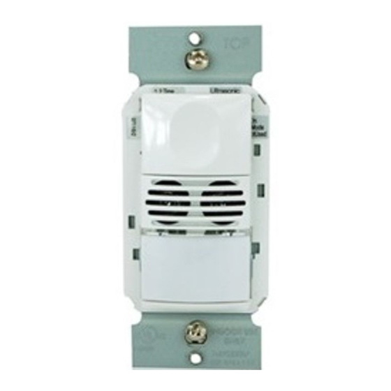
UNIT DESCRIPTION AND OPERATION
The WDT Dual Technology Multi-Way Wall Switch sensors combine advanced passive infrared (PIR) and ultrasonic
technologies into one unit. The combined technologies help to eliminate false triggering even in difficult applications.
Selectable operating modes allow the sensor to turn a load ON, and hold it ON as long as either or both
technologies detect occupancy. It allows for up to 4 sensors to be connected to the same circuit. The first sensor
to detect occupancy will turn ON all the lights that are connected to the same circuit. After the room is unoccupied,
the last sensor that detected occupancy turns OFF all the lights once the time delay has expired. The occupant
can turn OFF the load at any time by pressing the ON/OFF button of any sensor that is connected to the circuit.
A "walk-through" mode can turn lights off after only 3 minutes if no activity is detected after 30 seconds following
an occupancy detection.
The WDT301 has one relay and one ON/OFF button. The WDT321 contains two relays and two ON/OFF buttons
to allow control of one or two loads independently. Pressing a button toggles the state of the corresponding relay.
Optional Neutral is also available on all models.
WDT sensors contain a light level sensor. If adequate daylight is present, the sensor holds the load OFF until light
levels drop, even if the area is occupied. In the WDT321, light level only affects the load on Relay 2. Users can
override this function by pressing the ON/OFF button. See the Light Level Adjustment section.
Turning Load(s) ON (ON Mode)
The relays are programmed independently for either Auto ON or Manual ON. In either mode, the load can be
turned ON or OFF using the ON/OFF button.
Manual ON
With an ON Mode DIP switch in the ON position, the occupant must press the
ON/OFF button to turn ON the load. The sensor keeps the load ON until no motion
DIP 8 ON for Relay 1
is detected for the selected time delay. There is a 30 second re-retrigger delay. If
DIP 9** ON for Relay 2
occupancy is detected during the delay, the sensor turns the load back ON. After the
re-trigger delay elapses the ON/OFF button must be pressed to turn ON the load.
Auto ON
With an ON Mode DIP switch in the OFF position, the load turns ON and OFF
automatically based on occupancy. If the load is turned OFF manually, Presentation
DIP 8 OFF for Relay 1
Mode operation applies. This prevents the load from turning ON automatically after it
DIP 9** OFF for Relay 2
was deliberately turned OFF. Pressing the button to turn lights ON returns the sensor
to Auto ON mode.
** WDT301: Switch 9 is not used. WDT302: Switch 9 default is ON to comply with CA Energy Commission Title 24
bi-level switching requirements.
Model #
Relay
Default ON Mode
WDT301
1
Manual ON
WDT321
1
Auto ON
2
Manual ON
Presentation Mode
Presentation Mode is a feature of the Auto ON mode.When both relays are manually turned OFF the WDT holds
the lights OFF until no motion has been detected for the duration of the Time Delay. With subsequent occupancy,
the WDT turns the load ON. If both relays are ON and one relay is manually turned OFF this relay remains OFF
until both the Time Delay and retrigger delay expires for the relay that is ON, after that time the ON Mode control
settings again apply.
Time Delays
The WDT sensor holds the load ON until no motion is detected for the selected time delay. Select the time delay
using DIP switch settings. In the WDT321, both relays use the same delay. See DIP SWITCH SETTINGS for
more information.
Test/20 min
A Test Mode with a short time delay of five seconds is set when DIP switches 1 &
2 are OFF. It cancels automatically after ten minutes, or when you set a fixed time
(DIP 1, 2, OFF)
delay. When the Test Mode times out, the sensor will assume a 20 minute time delay.
To restart Test Mode, change the time delay setting to any fixed amount and then
return it to the Test setting.
Time Delay
Time delays are 5, 15 (default), or 30 minutes are available.
(15 min. DIP 1 ON &
2 OFF)
Walk-Through
The Walk-Through mode shortens the time delay to reduce the amount of time the load is ON after a brief moment
of occupancy, such as returning to an office to pick up a forgotten item then immediately exiting.
Walk-Through Mode
The WDT sensor turns the load OFF 3 minutes after the area is initially occupied if
no motion is detected after the first 30 seconds. If motion continues beyond the first
(DIP #3 ON)
30 seconds, the set time delay applies.
No Walk-Through
Walk-Through mode disabled (default).
PIR Sensitivity Adjustment
The WDT sensor constantly monitors the controlled environment and automatically adjusts the PIR to avoid
common ambient conditions that can cause false detections, while providing maximum coverage.
High
Default setting. Suitable for most applications.
(DIP #5 OFF)
Low, 50%
Reduces sensitivity by approximately 50%. Useful in cases where the PIR is detecting
movement outside of the desired area (also consider masking the lens) and where
(DIP #5 ON)
heat sources cause unnecessary activation.
Alerts
The WDT can provide audible alerts as a warning before the load turns OFF.
Audible Alerts
Unit will beep at one minute*, at 30 seconds and at 10 seconds before turning OFF
load. When Walk-Through is active, the unit beeps three times at 10 seconds before
(DIP #7 ON)
the load goes OFF.
No Audible Alerts
No audible warnings provided.
(DIP #7 OFF)
Trigger Mode
The WDT sensor has four occupancy trigger options, set with DIP switches 5 and 6. Determine the appropriate
option using the Trigger matrix.
In the Trigger Mode DIP switch setting table, in order to deem the area occupied:
•
Both requires motion detection by the PIR and the Ultrasonic.
•
Either requires motion detection by only one technology.
•
PIR requires motion detection by the PIR.
Initial Occupancy: The method that activates a change from "Standby"
(area unoccupied and load off) to "Occupied" (area occupied and load may
turn ON).
Maintain Occupancy: The method indicating that the area is still occupied
and the lights should remain ON.
Re-trigger: In Auto On Mode, after the load turns off, detection by the selected technology within the number
of seconds indicated turns the lights back ON. If the load was configured as Manual ON, the re-trigger time is
30 seconds.
@120 VAC .............................................. 1000-W tungsten, ballast, E-ballast, LED, 1/4 HP
@277 VAC .............................................................. 1200-W ballast, E-ballast, LED, 1/4 HP
@120 VAC ................................................ 800-W tungsten, ballast, E-ballast, LED, 1/6 HP
@277 VAC .............................................................. 1200-W ballast, E-ballast, LED, 1/6 HP
DIP switch #
Setting
8
ON
8
OFF
9
ON
Trigger
Mode
Standard
Both
Option A
PIR
Option B
PIR
Option C
Both
Pass & Seymour
Dual Technology Multi-Way Wall Switch Occupancy Sensor
Installation Instructions
Test Mode ................................................................................. 10 min. with 5-sec. time delay
PIR Adjustment ......................................................................................................High or Low
Ultrasonic Adjustment .....................................................................Minimum to Maximum, Off
Frequency ...................................................................................................................40 kHz
Light Level Adjustment ......................................................................................... 8fc to 180+fc
Alerts .............................................................................................Selectable Audible & Visual
Optional Neutral ....................................................................................................... All models
Multi-Way Capability................................................................................................. All models
Terminal screw torque ...............................................................................16 lbf-in (18 kgf-cm)
COVERAGE PATTERNS
Coverage testing has been performed according to the NEMA WD 7 guideline. For best performance, use in spaces
not larger than 18' x 15'.
PIR Sensor
The sensor has a two-tiered, multi-cell viewing Fresnel
lens with 180 degree field of view. The red LED on the
sensor flashes when the PIR detects motion.
Masking the Lens
Opaque adhesive tape is supplied so that sections of
the PIR sensor's view can be masked. This allows you
to eliminate coverage in unwanted areas. Since masking
removes bands of coverage, remember to take this into
account when troubleshooting coverage problems.
Ultrasonic Sensor
The sensor has two ultrasonic transceivers operating at
40 kHz. Detection sensitivity can be adjusted using the
trimpot under the ON/OFF buttons.
4'
(1.2m)
0
Side View
ADJUSTMENTS
Sensor Adjustment
Remove the wall plate. Remove the button cap by firmly squeezing together the top sides of the button assembly.
Gently pull it away from the unit.
When the adjustments are completed, replace the button cap by inserting its hinges into the tabs on the main unit
and then squeeze the top of the button while pressing it into the unit. Reinstall the cover plate.
Light Level Adjustment
The light level can be set with loads ON or OFF. To enable light level control and set the threshold:
1. Make sure the room is lit appropriately.
2. Put the sensor into TEST mode (see Time Delay switches). You have 10 minutes to complete the procedure.
3. Press and hold the ON/OFF button (Relay 1 button on the WDT321) for 3 seconds, until you hear a beep.
4. Step away from the sensor. After 10 seconds a beep sounds, indicating that the threshold level is set. This
threshold is retained, even if power is lost, until it is re-set or disabled. In the WDT321, light level control only
affects Relay 2.
To disable light level control, press and hold the Relay 1 button for 7 seconds until a double beep tone sounds.
Reset to Default
Use the DIP Switch Settings tables to return features to factory settings. To reset the WDT, press and hold the
Relay 1 button for 10 seconds until a triple beep sounds. This resets the sensor and disables light level control
(the brightest ambient light will not hold the light OFF).
INSTALLATION
Turn off the power at the circuit breaker before installing
1. Make sure that the power has been turned OFF at the circuit breaker.
2. Connect wires to the WDT flying leads as shown in the wiring diagram that is appropriate
to the WDT model and electrical supply. The ground wire (green) must be fastened
to ground for the sensor to work properly.
3. Attach the sensor to the wall box by inserting screws into the two wide holes on the top
and bottom of the attached metal bracket. Match them up with the holes in the wall box
and tighten.
4. Turn the circuit breaker ON. Wait one minute, then push the Auto ON/OFF switch for each load and the lights
will turn ON. There is a delay due to initial power-up of the sensor that only occurs during installation.
5. Test and adjust the sensor if necessary.
6. Install industry standard decorator wall switch cover plate (not included).
Black
Line
Green
Ground
Neutral
WDT301 Wiring
Neutral
Black
Line 1
Blue
Line 2
Green
Ground
Neutral
WDT321 Dual Circuit Wiring
OPTIONAL NEUTRAL WIRING
For applications requiring neutral wiring, remove tab as shown to expose terminals for wiring.
8" flying leads for
line, load, ground and
5 6
multi-way connections
Either
Either (5)
Yellow
Either Either (5)
PIR
PIR (5)
Both Both (5)
Red
Breakaway tab
Neutral Optional Wiring
®
Major motion
Minor motion
PIR
Coverage
35'
(10.6m)
20'
(6.1m)
35'
15'
13'
(4.5m)
(10.6m)
(4.0m)
WARNING
the sensor or working on the load.
Black
Red
Line
Load
Blue
Yellow
Neutral
Green
(optional)
Ground
Neutral
WDT321 Bi-Level Wiring
Red
Primary
Load
Yellow
Brown
Secondary
Load
Neutral
(optional)
WDT321 shown.
The WDT301 does not
include these two leads
Blue
Brown
Black
Green
Optional neutral
terminals behind
breakaway tab
Major motion
Minor motion
Ultrasonic
Coverage
13'
(4.0m)
10'
(3.0m)
7.5'
7.5'
(2.2m)
(2.2m)
10'
(3.0m)
Top View
Strip Gage
1/2"
12.7 mm
Copper Wire Only
#12 – #14 AWG
Red
Primary
Load
Yellow
Brown
Secondary
Load
Neutral
(optional)
Advertisement

Related Manuals for LEGRAND Pass & Seymour WDT301


Summary of Contents for LEGRAND Pass & Seymour WDT301
- Page 1 Pass & Seymour ® Dual Technology Multi-Way Wall Switch Occupancy Sensor No: 341098 – 10/14 Installation Instructions Catalog Numbers: WDT301, WDT321 Country of Origin: Made in China SPECIFICATIONS Voltages: ..................... 120/277 VAC, 50/60 Hz Test Mode ................. 10 min. with 5-sec. time delay Load Limits for relay 1: PIR Adjustment ......................High or Low @120 VAC ..........
- Page 2 30 seconds to be detected for the Legrand WDT series wall switches fit behind industry standard decorator-style switch cover plates. Cover plates are sensor to turn the load back on automatically. After the re-trigger delay elapses, not included.
Need help?
Do you have a question about the Pass & Seymour WDT301 and is the answer not in the manual?
Questions and answers