Table of Contents
Advertisement
Quick Links
SPLIT-TYPE, HEAT PUMP AIR CONDITIONERS
SPLIT-TYPE, AIR CONDITIONERS
SERVICE MANUAL
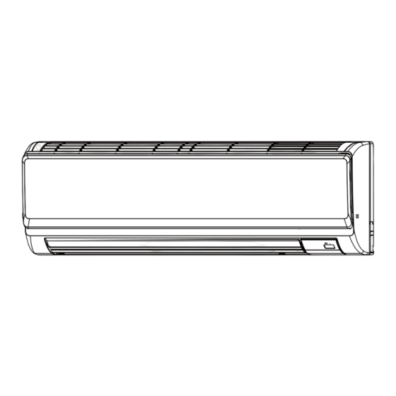
Indoor unit
[Model Name]
PKA-RP35HAL
PKA-RP50HAL
INDOOR UNIT
[Service Ref.]
PKA-RP35HAL
PKA-RP35HALR1
PKA-RP35HALR1-ER
PKA-RP50HAL
PKA-RP50HALR1
PKA-RP50HALR1-ER
CONTENTS
1. REFERENCE MANUAL ................................... 2
2. SAFETY PRECAUTION ................................... 3
3. PARTS NAMES AND FUNCTIONS ................. 4
4. SPECIFICATIONS ............................................ 6
5. NOISE CRITERION CURVES .......................... 7
6. OUTLINES AND DIMENSIONS ....................... 8
7. WIRING DIAGRAM .......................................... 9
8. REFRIGERANT SYSTEM DIAGRAM ............ 10
9. TROUBLESHOOTING .................................... 11
10. SPECIAL FUNCTION ..................................... 27
11. DISASSEMBLY PROCEDURE ....................... 30
PARTS CATALOG (OCB453)
July 2014
No. OCH453
REVISED EDITION-A
Revision:
• Added
PKA-RP35HALR1,
PKA-RP35HALR1-ER,
PKA-RP50HALR1 and
PKA-RP50HALR1-ER in
REVISED EDITION-A.
• Some descriptions have
been modified.
• Please void OCH453.
Notes:
• This manual describes
service data of the
indoor units only.
• RoHS compliant prod-
ucts have <G> mark on
the spec name plate.
Advertisement
Table of Contents

Related Manuals for Mitsubishi Electric Mr.SLIM PKA-RP35HALR1


Summary of Contents for Mitsubishi Electric Mr.SLIM PKA-RP35HALR1
-
Page 1: Table Of Contents
SPLIT-TYPE, HEAT PUMP AIR CONDITIONERS SPLIT-TYPE, AIR CONDITIONERS July 2014 No. OCH453 REVISED EDITION-A SERVICE MANUAL Indoor unit Revision: • Added [Model Name] [Service Ref.] PKA-RP35HALR1, PKA-RP35HAL PKA-RP35HALR1-ER, PKA-RP35HAL PKA-RP50HALR1 and PKA-RP50HALR1-ER in PKA-RP35HALR1 REVISED EDITION-A. • Some descriptions have been modified. -
Page 2: Reference Manual
TECHNICAL CHANGES Service ref. have been changed as follows. PKA-RP35HAL PKA-RP35HALR1 PKA-RP50HAL PKA-RP50HALR1 • S/W (for dual set temperature) has been changed. REFERENCE MANUAL OUTDOOR UNIT’S SERVICE MANUAL Service Manual No. Model Name Service Ref. PUHZ-RP35/50/60/71VHA4 PUHZ-RP35/50/60/71VHA4 OCH451 PUHZ-RP100/125/140VKA PUHZ-RP100/125/140VKA OCB451 PUHZ-RP100/125/140/200/250YKA PUHZ-RP100/125/140/200/250YKA... -
Page 3: Safety Precaution
SAFETY PRECAUTION 2-1. ALWAYS OBSERVE FOR SAFETY Before obtaining access to terminal, all supply circuits must be disconnected. 2-2. CAUTIONS RELATED TO NEW REFRIGERANT Cautions for units utilising refrigerant R410A Use a vacuum pump with a reverse flow check Use new refrigerant pipes. valve. -
Page 4: Parts Names And Functions
Unit Gravimeter [3] Service tools Use the below service tools as exclusive tools for R410A refrigerant. Tool name Specifications Gauge manifold · Only for R410A · Use the existing fitting specifications . (UNF1/2) · Use high-tension side pressure of 5.3MPa·G or over. Charge hose ·... - Page 5 3-2. Wireless remote controller CHECK TEST RUN display CHECK and TEST RUN display indicate that the unit is being checked or test-run. MODEL SELECT display Blinks when model is selected. display Lights up while the signal is transmitted to the indoor unit when the button is pressed. display SET TEMP.
-
Page 6: Specifications
SPECIFICATIONS Service Ref. PKA-RP35HAL PKA-RP35HALR1 PKA-RP35HALR1-ER Mode Cooling Heating Power supply (phase, cycle, voltage) Single phase, 50Hz, 230V Input 0.04 0.03 Running current 0.40 0.30 External finish (Panel) Munsell 1.0Y 9.2/0.2 Heat exchanger Plate fin coil Fan (drive) o No. Line flow fan (direct) o 1 Fan motor output 0.030... -
Page 7: Noise Criterion Curves
NOISE CRITERION CURVES 5-1. SOUND LEVELS Sound level at anechoic room : Low-Middle-High Sound level dB (A) Model PKA-RP35/50HAL 36 - 40 - 43 1.0m Measurement location * Measured in anechoic room. 5-2. NOISE CRITERION CURVES 70.0 High 65.0 60.0 NC-60 55.0 50.0... -
Page 8: Outlines And Dimensions
OUTLINES AND DIMENSIONS PKA-RP35HAL PKA-RP50HAL PKA-RP35HALR1 PKA-RP50HALR1 PKA-RP35,50HAL Unit : mm PKA-RP35HALR1-ER PKA-RP50HALR1-ER OCH453A... -
Page 9: Wiring Diagram
WIRING DIAGRAM PKA-RP35HAL PKA-RP50HAL PKA-RP35HALR1 PKA-RP50HALR1 PKA-RP35HALR1-ER PKA-RP50HALR1-ER [Explanation of symbols] Symbol Name Symbol Name Indoor controller board Vane motor CN2L Connector (LOSSNAY) Fan motor CN32 Connector ( Remote switch) Switch board CN41 Connector (HA terminal-A) SWE2 Emergency operation CN51 Connector (Centrally control) Terminal block(Indoor unit Power (option)) CN90... -
Page 10: Refrigerant System Diagram
REFRIGERANT SYSTEM DIAGRAM PKA-RP35HAL PKA-RP50HAL PKA-RP35HALR1 PKA-RP50HALR1 PKA-RP35HALR1-ER PKA-RP50HALR1-ER Strainer (#50) Heat exchanger Refrigerant GAS pipe connection (Flare) Thermistor TH2 Refrigerant flow in cooling (Pipe temperature/liquid) Refrigerant flow in heating Thermistor TH5 (Cond./ Eva.temperature) Refrigerant LIQUID pipe connection (Flare) Thermistor TH1 (Room temperature) Strainer (#50) Distributor... -
Page 11: Troubleshooting
TROUBLESHOOTING 9-1. TROUBLESHOOTING <Check code displayed by self-diagnosis and actions to be taken for service (summary)> Present and past check codes are logged, and they can be displayed on the wired remote controller or controller board of out- door unit. Actions to be taken for service, which depends on whether or not the trouble is reoccurring in the field, are summa- rized in the table below. - Page 12 9-2. MALFUNCTION-DIAGNOSIS METHOD BY REMOTE CONTROLLER <In case of trouble during operation> When a malfunction occurs to air conditioner, both indoor unit and outdoor unit will stop and operation lamp blinks to inform unusual stop. < Malfunction-diagnosis method at maintenance service> [Procedure] 1.
- Page 13 • Refer to the following tables for details on the check codes. [Output pattern A] Beeper sounds Beep Beep Beep Beep Beep Beep Beep OPERATION · · · Repeated INDICATOR lamp flash pattern Approx. 2.5 sec. 0.5 sec. 0.5 sec. 0.5 sec.
- Page 14 • If the unit cannot be operated properly after test run, refer to the following table to find the cause. Symptom Cause Wired remote controller LED 1, 2 (PCB in outdoor unit) •For about 2 minutes following power-on,op- For about 2 After LED 1, 2 are lighted, LED 2 is PLEASE WAIT minutes after...
- Page 15 Note: Errors to be detected in outdoor unit, such as codes starting with F, U or E (excluding E0 to E7), are not covered in this document. Please refer to the out- 9-3. SELF-DIAGNOSIS ACTION TABLE door unit's service manual for the details. Abnormal point and detection method Countermeasure Check code...
- Page 16 Abnormal point and detection method Countermeasure Check code Cause (Cooling or drying mode) (Cooling or drying mode) Freezing/overheating protection is work- 1 Clogged filter (reduced airflow) 1 Check clogs of the filter. 1 Freezing protection (Cooling mode) 2 Short cycle of air path 2 Remove shields.
- Page 17 Abnormal point and detection method Countermeasure Check code Cause 1 Defective thermistor Pipe temperature thermistor/ characteristics 1–3 Check resistance value of thermistor. Condenser-Evaporator (TH5) For characteristics, refer to (P1) above. 1 The unit is in 3-minute resume protec- 2 Contact failure of connector 2 Check contact failure of connector (CN44) tion mode if short/open of thermistor is (CN44) on the indoor controller...
- Page 18 Abnormal point and detection method Countermeasure Check code Cause 1 Set a remote controller to main, and the Remote controller transmission 1 2 remote controllers are set as other to sub. error(E3)/signal receiving error(E5) 1 Abnormal if remote controller could not “main.”...
- Page 19 Abnormal point and detection method Countermeasure Check code Cause 1 Drain pump trouble 1 Check the drain pump. Forced compressor stop (due to water leakage abnormality) 1 The unit has a water leakage abnor- 2 Drain defective 2 Check whether water can be drained. mality when the following conditions, a) ·...
- Page 20 9-4. TROUBLESHOOTING BY INFERIOR PHENOMENA Note: Refer to the outdoor unit's service manual for the detail of remote controller. Phenomena Cause Countermeasure • When LED1 on indoor controller board is also off. (1)LED2 on indoor controller board 1 Power supply of rated voltage is not supplied to out- 1 Check the voltage of outdoor power is off.
- Page 21 Note: Refer to the outdoor unit's service manual for the detail of remote controller. Phenomena Cause Countermeasure • When LED1 on indoor controller board is also blinking. Check indoor/outdoor unit connecting wire (2)LED2 on indoor controller board Connection failure of indoor/outdoor unit connecting for connection failure.
- Page 22 9-5. EMERGENCY OPERATION 9-5-1. When wireless remote controller fails or its battery is exhausted When the remote controller cannot be used When the batteries of the remote controller run out or the remote controller malfunctions, the emergency operation can be done using the emergency buttons.
- Page 23 9-6. HOW TO CHECK THE PARTS PKA-RP35HAL PKA-RP50HAL PKA-RP35HALR1 PKA-RP50HALR1 PKA-RP35HALR1-ER PKA-RP50HALR1-ER Parts name Check points Room temperature Disconnect the connector then measure the resistance using a tester. thermistor (TH1) (At the ambient temperature 10 to 30:) Pipe temperature Normal Abnormal thermistor/liquid (TH2) Refer to “9-6-1.
- Page 24 9-6-2. DC Fan motor (fan motor/indoor controller circuit board) Check method of DC fan motor (fan motor/indoor controller circuit board) Notes · High voltage is applied to the connecter (CNMF) for the fan motor. Pay attention to the service. · Do not pull out the connector (CNMF) for the motor with the power supply on. board and fan motor.) (It causes trouble of the indoor controller circuit Self check...
- Page 25 9-7. TEST POINT DIAGRAM Indoor controller board PKA-RP35HAL PKA-RP50HAL PKA-RP35HALR1 PKA-RP50HALR1 PKA-RP35HALR1-ER PKA-RP50HALR1-ER CNMF Connect to the fan motor (MF) 1–3 : 310–340 V DC 4–3 : 15 V DC 5–3 : 0–6.5 V DC 6–3 : 0 or 15 V DC CN105 CN01 Connect to the...
- Page 26 9-8. FUNCTIONS OF DIP SWITCH AND JUMPER WIRE Each function is controlled by the DIP switch and the jumper wire on the indoor controller board. (Marks in the table below) Jumper wire ( : Short : Open) Jumper wire Setting by the dip switch and jumper wire Remarks Functions MODELS...
-
Page 27: Special Function
SPECIAL FUNCTION 10-1. ROTATION FUNCTION(AND BACK-UP FUNCTION, 2ND STAGE CUT-IN FUNCTION) Optional wired remote controller with terminal bed (PAR-21MAAT-E) are necessary for PKA type. 10-1-1. Operation (1) Rotation function (and Back-up function) • Outline of functions · Main and sub unit operate alternately according to the interval of rotation setting. Main and sub unit should be set by refrigerant address. - Page 28 • System constraint · This function is available only in cooling mode. [2nd stage cut-in function]··· Request code number "322~324" Ex.) Set temp. by R/C = 20: Set point = 26: Room temp. ] Set point Room temp. < Set point -4: When request code number is “323”.
- Page 29 (2) Setting method of each function by wired remote controller B: Refrigerant address C: Data display area D: Request code display area 1. Stop operation(1). 2. Press the button (2) for 3 seconds so that [Maintenance mode] appears on the screen (A). TEST After a while, [00] appears in the refrigerant address number display area.(at B ) 3.
-
Page 30: Disassembly Procedure
DISASSEMBLY PROCEDURE PKA-RP35HAL PKA-RP50HAL PKA-RP35HALR1 PKA-RP50HALR1 Be careful when removing heavy parts. PKA-RP35HALR1-ER PKA-RP50HALR1-ER OPERATION PROCEDURE PHOTOS & ILLUSTRATIONS 1. Removing the lower side of the indoor unit from the Figure 1 installation plate (1) Remove the front panel. (2) Insert the screw driver to the corner hole at both left and right side as shown in the figure 1. - Page 31 OPERATION PROCEDURE PHOTOS 3. Removing the indoor controller board and wireless Photo 3 Electrical box cover (top) Electrical box controller board Screw (side cover) cover (side) Screw (top cover) (1) Remove the front panel. (Refer to 2.) (2) Remove the room temp. thermistor TH1. (see Photo 3) (3) Remove the electrical box covers (screw 4 ×...
- Page 32 OPERATION PROCEDURE PHOTOS Electrical box cover (side) 5. Removing the nozzle assembly (with vane and vane Electrical box cover (top) Photo 8 motor) and drain hose Screw (side cover) Screw (top cover) (1) Remove the front panel (Refer to 2.). (2) Remove the electrical box cover.
- Page 33 OPERATION PROCEDURE PHOTOS 9. Removing the heat exchanger Photo 14 Electrical box cover (side) Electrical box cover (top) (1) Remove the front panel (Refer to 2.) and the corner panel Heat exchanger Screw (side cover) at right lower side. Screw (top cover) Water cover (2) Remove the electrical box (Refer to 4.) and the nozzle assembly (Refer to 5.).
- Page 34 HEAD OFFICE : TOKYO BLDG., 2-7-3, MARUNOUCHI, CHIYODA-KU, TOKYO 100-8310, JAPAN CCopyright 2009 MITSUBISHI ELECTRIC CORPORATION New publication, effective Jul. 2014 Distributed in Jul. 2014 No.OCH453 REVISED EDITION-A Specifications are subject to change without notice. Distributed in Mar. 2009 No.OCH453 PDF 7...