
Related Manuals for Broil King P4X Series


Summary of Contents for Broil King P4X Series
- Page 1 P R E M I U M G R I LL S SERIES SERIES P3X(N)-5, P3SX(N)-5, P3XF(N)-5, P4X(N)-3, P4XF(N)-3 P3X AND P4X GRILL HEAD GAS-FIRED...
- Page 2 IMPORTANT INFORMATION IMPORTANT his manual should be read thoroughly by the installer and by anyone who will use or maintain the grill. Installer - Write the model number, serial number, and date of installation in the manual. If available, attach a copy of the receipt. Leave this manual with the grill owner. Grill Owner - Read and retain this manual.
- Page 3 Thank you for purchasing a Premium Gas Grill. Broilmaster takes pride in its reputation as the The Most Durable Grill Known to Man. From its thick aluminum casting to its massive cooking grids, your Broilmaster is built to last. In fact we still make replacement parts for Broilmaster grills built more than 30 years ago.
-
Page 4: Table Of Contents
Please take time to read this entire manual before assembling your Premium Broilmaster gas grill. ASSEMBLY INSTRUCTIONS ..................... 5 P3X SERIES PARTS DIAGRAM ....................6 P4X SERIES PARTS DIAGRAM ....................7 GRILL HEAD HARDWARE PACK - B102529 ................8 UNPACK AND REMOVE LID ..................... 9 INSERT BURNER HOLD-DOWN BOLT .................. -
Page 5: Assembly Instructions
ASSEMBLY INSTRUCTIONS BEFORE YOU BEGIN This Grill Head requires Broilmaster Mounting (Cart, Post, or a Built-In Kit). See Mounting Instructions to assemble mounting before Assembling Grill Head. Compare the parts in the box to the parts list provided in this manual. If any are missing, contact your Broilmaster dealer before beginning assembly. -
Page 6: P3X Series Parts Diagram
P3X SERIES PARTS DIAGRAM DPP155 B101883 (1) GRILL BODY TOP B102042 (1) TOP WITH HEAT INDICATOR, HINGE B073097 (1) FOAM GRIP B102492 (1) LID HANDLE (W/SCREWS) B101420 (1,LP) OR B101421 (1,NAT) VALVE LPG OR NATURAL B072695(1) P182 (2, LP) P265 (2, NAT) RETRACTING RACK ORIFICE LPG OR NATURAL DPA111 (1) -
Page 7: P4X Series Parts Diagram
P4X SERIES PARTS DIAGRAM DPP155 B102043 (1) GRILL BODY TOP B076621 (1) TOP WITH HEAT INDICATOR, HINGE B073097 (1) FOAM GRIP B102492 (1) LID HANDLE (W/SCREWS) B101420 (1,LP) OR B101421 (1,NAT) VALVE LPG OR NATURAL B072696(1) P182 (2, LP) P265 (2, NAT) -
Page 8: Grill Head Hardware Pack - B102529
GRILL HEAD HARDWARE PACK - B102529 SPACER PHILLIPS PAN HEAD SCREW, PHILLIPS PAN HEAD SCREW, PHILLIPS TRUSS HEAD SCREW, SS,1/4-20 X 1-1/2 SS,10-24 X 1 10-24 X 3/4 B662325 B101649 B073978 B100128 HEX NUT, HEX LOCKNUT, KEPS NUT, FLAT WASHER, COTTER PIN SS,1/4-20 SS,10-24... -
Page 9: Unpack And Remove Lid
UNPACK AND REMOVE LID REMOVING LID To ease assembly, remove Grill Lid and Warming Rack. Remove Warming Rack and set aside. Remove the two Pins and Clips at the rear of the Grill Prior to assembling Grill Head Lid and set aside. After Pins, Lid and assemble Cart or Post mounting first. -
Page 10: Insert Burner Hold-Down Bolt
INSERT BURNER HOLD-DOWN BOLT PHILLIPS PAN HEAD SCREW SS, 1/4-20 X 1-1/2 B101649 (1) HEX NUT, SS, 1/4-20 B076331(1) 7/16” After the Securing Bolt has been installed, proceed and Install Grill Head on a Cart or Post Mounting. (See Grill Head on a Cart or Post Mounting Instructions that come with the mounting option). -
Page 11: Wind Deflector Placement
WIND DEFLECTOR PLACEMENT Place the Wind Deflector in the bottom Casting. The Wind Deflector cannot be installed until after the bottom Casting is installed on theCart or Post. B102521-0-0219 Page 11... -
Page 12: Insert Collector Box
INSERT COLLECTOR BOX KEPS NUT, SS, 10-24 B073967(2) 9/16” Install collector box with this edge facing up and parallel to bottom surface of grill. Note: If a side shelf accessory is to be used, install it at this time. Refer to side shelf installation instructions for more information. -
Page 13: Attach Ignitor Wire, Insert Control Panel
ATTACH IGNITOR WIRE, INSERT CONTROL PANEL KEPS NUT, SS, 10-24 B073967(2) 3/8” Attach the ground wire to the ground lug. Slide both the ground wire and electrode wire through the hole in the center of the Control Panel Shield. Ease the Control Panel Shield over the studs on the Control Panel. -
Page 14: Install Burner Assembly
INSTALL BURNER ASSEMBLY COTTER PIN, B057805(1) Slide the Venturi onto the Valve Insert the Burner Assembly into Assembly as shown. the Grill bottom with the Venturi Tubes facing the front of the Grill. Raise end of the Burner Bracket and slip it over the Phillips Truss Head Screw. -
Page 15: Connect Ignitor Leads
CONNECT IGNITOR LEADS IGNITOR Route Leads from Collector Box and secure to Ignitor Terminals (polarity is not important). If Side Shelf Accessory was purchased The Ignitor terminals do install at this time. Follow Side Shelf not have a polarity. B102521-0-0219 Page 15... -
Page 16: Knob And Battery Placement
KNOB AND BATTERY PLACEMENT Unscrew the Ignitor Knob from the Control Panel, and insert AA Battery, positive side up, and replace Ignitor Button. AFTER Page 16 B102521-0-0219... -
Page 17: Install Lid Stop
INSTALL LID STOP PHILLIPS TRUSS HEAD SCREW, SS,10-24 X 3/4 B100128 (1) HEX LOCK NUT, SS, 10-24 R4021 (1) 3/8” FLAT WASHER 1/4 x 5/8 OD B076332 (2) SPACER, B662325 (1) LID STOP Screw the black Knob onto the Lid Stop. -
Page 18: Handle Installation
HANDLE INSTALLATION Handle is shipped with screws installed. Remove the screws, align handle with top casting, and re-install screws. Tip: For ease of installation, lightly lubricate the inside of the Foam Grip with Liquid Soap before twisting it on to Handle. -
Page 19: Reinstall Lid
REINSTALL LID HINGE PIN, (FROM PREVIOUS STEPS) B057804 (2) COTTER PIN, (FROM PREVIOUS STEPS) B057805 (2) B102521-0-0219 Page 19... -
Page 20: P3Xf(N), P4Xf(N) Flare Busters And Racks
P3XF(N), P4XF(N) FLARE BUSTERS AND RACKS P3SXF(N) MODELS P4XF(N) MODELS Position the Flare Busters as shown Position the Flare Busters as shown Page 20 B102521-0-0219... -
Page 21: P3Sx(N) Flare Busters,Smoker Shutter And Racks
P3SX(N) FLARE BUSTERS,SMOKER SHUTTER AND RACKS When installing Griddle, in your P3X Gill, please use the Griddle installation instructions provided with Griddle. P3SX(N) MODELS Position the Flare Busters as shown For Smoker Shutter Installation See Illustrated Instructions included with your smoker shutter accessory. Note: When using the Smoker Shutter the Cooking Grids can not be used in the lowest setting. -
Page 22: P3X(N) And P4X(N) Briquets And Racks
P3X(N) AND P4X(N) BRIQUETS AND RACKS Place the 'Char-Master' Briquets in a single layer evenly on your grill's briquet rack. DO NOT dump them onto the briquet rack. A single layer of 'Char-Master' Briquets works best. Save leftover briquets for future use. -
Page 23: Install Warming Rack
INSTALL WARMING RACK B102521-0-0219 Page 23... -
Page 24: Propane Gas Grills
PROPANE GAS GRILLS 3/4” For Natural Gas Grills please proceed to page 28. Attach the LP hose and Regulator to the fitting on the Burner Control Valve mounted on the Control Panel. Tighten this connection with a wrench. LP GAS REGULATOR AND HOSE Page 24 B102521-0-0219... - Page 25 PROPANE GAS GRILLS Failure to follow these safety precautions could result in Grill Location a fire or explosion causing property damage or personal This grill is designed for outdoor use only. injury. Never operate your grill in any building, garage, or other Use extreme caution when handling propane gas cylinders.
- Page 26 PROPANE GAS GRILLS Propane Cylinder Requirements ATTENTION: Propane gas cylinders must comply with Cylinder Requirements and Connection Requirements above. Your Broilmaster Premium Gas Grill requires a standard 20-lb propane gas cylinder, which is available from your grill dealer, Note: Not all valve and cylinder combinations are compatible. your LP supplier, and at most hardware and home stores.
- Page 27 PROPANE GAS GRILLS Pressure Regulator and Hose Assembly The pressure regulator has an outlet pressure of not more than eleven inches water column. It must be connected to the Propane gas cylinder’s female valve outlet before the grill can be operated. Make sure the grill’s burner controls are off.
-
Page 28: Connecting Natural Gas Grill
CONNECTING NATURAL GAS GRILL 3/4” Attach the Natural Gas hose to the fitting on the Burner Control Valve mounted on the Control Panel. Snug this connection with a wrench. 12 FT QUICK DISCONNECT HOSE Not Supplied (Purchased Accessory, NG12) Page 28 B102521-0-0219... -
Page 29: Natural Gas Grills
NATURAL GAS GRILLS Connection Requirements Grill Location Broilmaster natural gas grills are not equipped with pressure This grill is designed for outdoor use only. regulators. Your gas grill operates at a manifold pressure of seven inches water column. (Your natural gas technician will Never operate your grill in any building, garage, or other understand what this means.) enclosed area. -
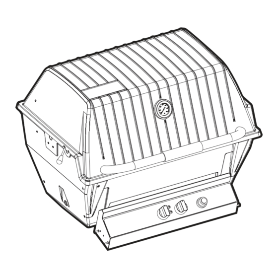
Page 30: Completed Assembly
COMPLETED ASSEMBLY Thank you for purchasing a Premium Gas Grill and we hope you enjoy years of great meals prepared on your Broilmaster. Please feel free to visit the Broilmaster Facebook page and share photos of your Broilmaster grill. Thank You! Page 30 B102521-0-0219... -
Page 31: Owner's Manual For P3X And P4X Grills
OPERATION - PROPANE AND NATURAL GAS GRILLS Check for Gas Leaks Operating Instructions Check for gas leaks every time you connect your Broilmaster Lighting with the Electric Ignitor propane gas grill to a Propane gas cylinder, when a connected cylinder has not been used recently, or when either a natural or propane grill is being used for the first time. - Page 32 OPERATION - PROPANE AND NATURAL GAS GRILLS Electrical Accessories Before Cooking Before cooking on a grill for the first time, burn off any oil residue If an electrical accessory (e.g. rotisserie) used on your grill must be electrically grounded in accordance with local codes or, in the from the manufacturing process.
-
Page 33: Maintenance
MAINTENANCE MAINTENANCE Cleaning the Grill To reduce risk, inspect and clean the venturi tubes at least twice per year and more often if spiders are active. If the grill has been unused for an extended period of time inspect the tubes CAUTION before using the grill. -
Page 34: Troubleshooting
TROUBLESHOOTING Although we have attempted to ensure that your grill will operate properly and satisfactorily, sometimes problems do arise. The following troubleshooting guide lists several possible problems and their probable cause and solution. Do not repair or replace any part of the grill unless specifically recommended in this manual. All other service should be referred to a qualified technician. -
Page 35: Important Safety Information
IMPORTANT SAFETY INFORMATION WARNING piders and insects can nest in gas grill burners causing the gas ignite under the control panel. This is very dangerous and can damage the grill, making it unsafe to operate. Inspect the grill at least twice per year and more often if spiders are active. Be sure all grill controls are turned off and the grill is cool before using any type of aerosol cleaner on or around the grill. - Page 36 IMPORTANT SAFETY INFORMATION Practice Safe Grilling Do not wear loose fitting clothing or flammable clothing (such as synthetics) around the grill. Never let clothing, pot holders, or other flammable materials come in contact with or too close to any grate, burner or hot surface.
-
Page 37: Cooking Tips
COOKING TIPS Cook Food To Proper Temperatures Cooking food safely requires that you raise the internal temperature of the meat high enough and for a long enough period of time to kill any food-borne bacteria that may cause illnesses. Color is not the best indicator that food is safe to eat. Use a high-quality probe thermometer to be sure your food is properly cooked. -
Page 38: Warranty Terms
WARRANTY TERMS Empire Comfort Systems Inc. warranties this Broilmaster premium gas grill to be free from defects at the time of purchase and for the periods specified below. Broilmaster Premium Gas Grills must be installed by a qualified tech- nician and must be maintained and operated safely, in accordance with the instructions in the owner’s manual. This warranty applies to the original purchaser only and is not transferable. -
Page 39: Master Parts Distributor List
MASTER PARTS DISTRIBUTOR LIST To order parts under warranty, please contact your local Broilmaster dealer. See the dealer locator at www.broilmaster.com. To provide warranty service, your dealer will need your name and address, purchase date and serial number, and the nature of the problem. -
Page 40: Grill Maintenance History
GRILL MAINTENANCE HISTORY Date Maintenance Performed PR EM IU M GR ILL S BROILMASTER A Division of Empire Comfort Systems, Inc. Belleville, Illinois .broilmaster.com isit our web site at www If you have a general question about our products, please e-mail us at info@empirecomfort.com. If you have a service or repair question, please contact your dealer.
Need help?
Do you have a question about the P4X Series and is the answer not in the manual?
Questions and answers