
Related Manuals for EWM TIG 260 F1 WD 5P


Summary of Contents for EWM TIG 260 F1 WD 5P
- Page 1 Operating instructions welding torch TIG 260 F1 WD 5P TIG 260 F1 WD U/D 8P 099-518352-EW501 Observe additional system documents! 07.06.2023...
- Page 2 +49 2680 181-0. A list of authorised sales partners can be found at www.ewm-group.com/en/specialist-dealers. Liability relating to the operation of this equipment is restricted solely to the function of the equipment. No other form of liability, regardless of type, shall be accepted.
-
Page 3: Table Of Contents
Contents Notes on using these operating instructions Contents 1 Contents ............................3 2 For your safety ..........................5 Notes on using these operating instructions ................ 5 Explanation of icons ......................6 Safety instructions ........................ 7 Transport and installation ....................10 3 Intended use .......................... - Page 4 Contents Notes on using these operating instructions 9 Accessories ..........................35 List of tools ......................... 35 Options ..........................35 Welding torch cooling system ..................... 35 9.3.1 Coolant - type blueCool ..................35 9.3.2 Coolant - type KF ....................35 10 Replaceable parts ........................36 10.1 TIG 260 F1 WD ........................
-
Page 5: For Your Safety
For your safety Notes on using these operating instructions For your safety Notes on using these operating instructions DANGER Working or operating procedures which must be closely observed to prevent imminent serious and even fatal injuries. • Safety notes include the "DANGER" keyword in the heading with a general warning symbol. •... -
Page 6: Explanation Of Icons
For your safety Explanation of icons Explanation of icons Symbol Description Symbol Description Indicates technical aspects which the Activate and release / Tap / Tip user must observe. Switch off machine Release Switch on machine Press and hold Incorrect / Invalid Switch Correct / Valid Turn... -
Page 7: Safety Instructions
For your safety Safety instructions Safety instructions WARNING Risk of accidents due to non-compliance with the safety instructions! Non-compliance with the safety instructions can be fatal! • Carefully read the safety instructions in this manual! • Observe the accident prevention regulations and any regional regulations! •... - Page 8 For your safety Safety instructions WARNING Risk of injury due to improper clothing! During arc welding, radiation, heat and voltage are sources of risk that cannot be avoided. The user has to be equipped with the complete personal protective equipment at all times.
- Page 9 For your safety Safety instructions CAUTION Smoke and gases! Smoke and gases may lead to shortness of breath and poisoning! The ultraviolet radia- tion of the arc may also convert solvent vapours (chlorinated hydrocarbon) into poiso- nous phosgene. • Ensure sufficient fresh air! •...
-
Page 10: Transport And Installation
For your safety Transport and installation CAUTION Obligations of the operator! The respective national directives and laws must be complied with when operating the machine! • Implementation of national legislation relating to framework directive 89/391/EEC on the int- roduction of measures to encourage improvements in the safety and health of workers at work and associated individual guidelines. - Page 11 For your safety Transport and installation CAUTION Risk of accidents due to supply lines! During transport, attached supply lines (mains leads, control cables, etc.) can cause risks, e.g. by causing connected machines to tip over and injure persons! • Disconnect all supply lines before transport! Risk of tipping! There is a risk of the machine tipping over and injuring persons or being damaged itself during movement and set up.
-
Page 12: Intended Use
3.2.1 Warranty For more information refer to the "Warranty registration" brochure supplied and our information regarding warranty, maintenance and testing at www.ewm-group.com! 3.2.2 Declaration of Conformity This product corresponds in its design and construction to the EU directives listed in the decla- ration. -
Page 13: Part Of The Complete Documentation
Intended use Documents which also apply 3.2.4 Part of the complete documentation This document is part of the complete documentation and valid only in combination with all other parts of these instructions! Read and observe the operating instructions for all system components, especially the safety instructions! The illustration shows a general example of a welding system. -
Page 14: Product Description - Quick Reference
Product description – quick reference Product variants Product description – quick reference Product variants Version Functions Rated output Water-cooled with decentral connection TIG 260 Double push-button control TIG 260 The welding power (welding current) can be reduced to the secondary current during the welding process. U/D 8P Control Up-/Down TIG 260... -
Page 15: Welding Fume Extractor
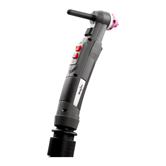
Product description – quick reference Welding fume extractor Welding fume extractor 4.2.1 TIG 260 F1 WD Figure 4-1 Item Symbol Description Back cap Bypass slider, extraction capacity Torch body Extraction nozzle with integrated gas nozzle Tungsten electrode Welding torch hose package Connection variants >... -
Page 16: Connection Variants
Product description – quick reference Welding fume extractor 4.2.2 Connection variants 4.2.2.1 Decentral connection (standard) Figure 4-2 4.2.2.2 Euro central connection Figure 4-3 4.2.2.3 Euro central connection - KOMBI Figure 4-4 Item Symbol Description Quick connect coupling, NW 5 Coolant return (red) Quick connect coupling, NW 5 Coolant feed (blue) 099-518352-EW501... - Page 17 Product description – quick reference Welding fume extractor Item Symbol Description Control lead cable plug Shielding gas hose Crown nut G ¼“ Welding current connection Decentral Euro central connection Welding current and shielding included. Euro torch connector – combination Shielding gas integrated, decentral welding current 099-518352-EW501 07.06.2023...
-
Page 18: Design And Function
Design and function General Design and function General WARNING Risk of injury from electrical voltage! Contact with live parts, e.g. power connections, can be fatal! • Observe the safety information on the first pages of the operating instructions! • Commissioning must be carried out by persons who are specifically trained in handling power sources! •... -
Page 19: Scope Of Delivery
Design and function Scope of delivery Scope of delivery The delivery is checked and packaged carefully before dispatch, however it is not possible to exclude the possibility of damage during transit. Receiving inspection • Check that the delivery is complete using the delivery note! In the event of damage to the packaging •... -
Page 20: Welding Torch Cooling System
All information relates to the total hose package length of the complete welding system and presents exemplary configurations (of components of the EWM product portfolio with standard lengths). A straight kink-free installation is to be ensured, taking into account the max. delivery height. -
Page 21: Wear Part Replacement
Design and function Wear part replacement Wear part replacement 5.4.1 Deinstallation/Installation When the welding quality deteriorates, the cause in most cases is worn electrodes and / or nozzles. To prevent damage to the welding torch, the replacement of wear parts must not be delayed unnecessarily. Before starting any work on the welding torch, the welding system must be switched off and secured against accidental re-start. -
Page 22: Electrode Replacement
Design and function Wear part replacement Item Symbol Description Gas diffuser Extraction nozzle with integrated gas nozzle • Unscrew and remove the extraction nozzle. • Loosen back cap by hand. • Pull out the tungsten electrode. • Loosen gas diffuser by hand. •... -
Page 23: Setting The Electrode Spacing
Design and function Wear part replacement Figure 5-4 The more pointed the grinding cone, the deeper the penetration. The blunter the grinding cone, the shallower the penetration. 5.4.2.2 Setting the electrode spacing Figure 5-5 Make sure of the correct electrode gap! 099-518352-EW501 07.06.2023... -
Page 24: Function Specification
Design and function Function specification Function specification 5.5.1 General TIG welding torches are connected to the power source via the hose package. The following components are guided through the hose package: • welding current lead • shielding gas supply • control cable and •... -
Page 25: Commissioning
Design and function Commissioning Item Symbol Description Torch trigger Up/Down function TIG Up/Down torches are equipped with two torch triggers. These triggers are used to: • switch the welding current on and off, • reduce the current to a secondary current by tapping it, •... -
Page 26: Maintenance, Care And Disposal
Maintenance, care and disposal General Maintenance, care and disposal General DANGER Risk of injury due to electrical voltage after switching off! Working on an open machine can lead to fatal injuries! Capacitors are loaded with electrical voltage during operation. Voltage remains present for up to four minutes after the mains plug is removed. -
Page 27: Improper Use
Maintenance, care and disposal General Torch connection • The thread of the crown nut is dirty or damaged. • For water-cooled welding torches, check the coolant connections for damage. Grip • Cracks, penetration Hose package • Cracks, penetration • Clogged welding fume extraction hoses 6.1.2 Improper use The illustration serves as an example only. -
Page 28: Maintenance And Care Before Each Use
Maintenance, care and disposal General 6.1.3 Maintenance and care before each use • Loosen the gas nozzle/extraction nozzle; check the replacement parts for damage; replace, if neces- sary, and ensure a tight fit. • Clean and remove soiling and welding spatter from the welding torch and, particularly, the wear parts; replace any worn or defective parts, if necessary. -
Page 29: Disposing Of Equipment
Information on returning used equipment or collections can be obtained from the respective municipal administration office. Devices can also be returned to EWM sales partners across Europe. Further information on the topic of the disposal of electrical and electronic equipment can be found on our website at: https://www.ewm-group.com/de/nachhaltigkeit.html. -
Page 30: Rectifying Faults
Rectifying faults Checklist for rectifying faults Rectifying faults All products are subject to rigorous production checks and final checks. If, despite this, something fails to work at any time, please check the product using the following flowchart. If none of the fault rectification procedures described leads to the correct functioning of the product, please inform your authorised dea- ler. - Page 31 Rectifying faults Checklist for rectifying faults Pore formation Inadequate or missing gas shielding Check shielding gas setting and replace shielding gas cylinder if necessary Shield welding site with protective screens (draughts affect the welding result) Check the O-rings on the Euro torch connector and torch neck and replace them if necessary. ...
-
Page 32: Vent Coolant Circuit
Rectifying faults Vent coolant circuit Vent coolant circuit Figure 7-1 • Switch off the machine and fill the coolant tank to the maximum level. • Unlock the quick-connect coupling with a suitable tool (connection open). To vent the cooling system always use the blue coolant connection, which is located as deep as possible inside the system (close to the coolant tank)! Figure 7-2 •... -
Page 33: Technical Data
Technical data TIG 260 F1 WD Technical data Performance specifications and guarantee only in connection with original spare and replacement parts! TIG 260 F1 WD Welding torch polarity Normally negative Guide type Manually operated Voltage type Direct voltage DC or Alternating voltage AC Shielding gas according to ISO 14175 Argon Duty cycle DC at 40°... -
Page 34: Definition Of Terms
Technical data TIG 260 F1 WD 8.1.1 Definition of terms The illustration serves as an example only. Figure 8-1 Item Symbol Description Flow-rate nozzle ∆ Vacuum connector Flow rate connector 099-518352-EW501 07.06.2023... -
Page 35: Accessories
Accessories List of tools Accessories Performance-dependent accessories like torches, workpiece leads, electrode holders or intermediate hose packages are available from your authorised dealer. List of tools Type Designation Item no. O-Ring Picker O-ring picker 098-005149-00000 Options Type Designation Item no. ON AA NW44 Adapter for welding fume extraction torch to 094-026782-00000... -
Page 36: Replaceable Parts
Replaceable parts TIG 260 F1 WD Replaceable parts 10.1 TIG 260 F1 WD The manufacturer's warranty becomes void if non-genuine parts are used! • Only use system components and options (power sources, welding torches, electrode hold- ers, remote controls, spare parts and replacement parts, etc.) from our range of products! •... -
Page 37: Service Documents
Service documents Circuit diagram Service documents 11.1 Circuit diagram The circuit diagrams are only intended for authorised service personnel! 11.1.1 Standard, up/down torches Figure 11-1 099-518352-EW501 07.06.2023... -
Page 38: Appendix
Appendix Altitude alignment Appendix 12.1 Altitude alignment The higher the altitude, the less vacuum is required at the connection piece ∆pc of the welding torch to achieve the required welding fume flow rate at the welding nozzle. Determine the corresponding factor in the following table: (Z) = f x ∆... -
Page 39: Searching For A Dealer
Appendix Searching for a dealer 12.2 Searching for a dealer Sales & service partners www.ewm-group.com/en/specialist-dealers "More than 400 EWM sales partners worldwide" 099-518352-EW501 07.06.2023...
Need help?
Do you have a question about the TIG 260 F1 WD 5P and is the answer not in the manual?
Questions and answers