Mitsubishi Electric CITY MULTI PAC-YT53CRAU Installation Manual
Hide thumbs
Also See for CITY MULTI PAC-YT53CRAU:
- Installation manual (49 pages) ,
- Instruction book (24 pages) ,
- Instruction book (24 pages)
Advertisement
Available languages
Available languages
Quick Links
CITY MULTI Control System
and Mitsubishi M-Series and P-Series Air Conditioners
Simple MA Remote Controller
Installation Manual
This installation manual describes how to install the Simple MA Remote Controller for use with
Mitsubishi Building Air Conditioning System, direct expansion type CITY MULTI air conditioner indoor
units ("-A" type and later), and Mitsubishi M-Series and P-Series packaged air conditioners.
Please be sure to read this installation manual and Instruction Book that are supplied with the Remote
Controller before proceeding with the installation. Failure to follow the instructions may result in
equipment damage.
For information on how to wire and install the air conditioning units, refer to the installation manual.
After the installation, hand over this manual to users.
1
Safety Precautions
• Read the following safety precautions prior to installation.
• Observe these precautions carefully to ensure safety.
WARNING
Indicates a risk of death or serious injury if you misuse the PAC-YT53CRAU.
Indicates a risk of serious injury or structural damage if you misuse the
CAUTION
PAC-YT53CRAU.
• After reading this manual, provide this manual to end user for future reference.
• Keep this manual for future reference and refer to it as necessary. This manual should be made
available to those who repair or relocate the controller. Make sure that the manual is forwarded to
future end users.
All electric work must be performed by qualified personnel.
General precautions
WARNING
Do not install the unit in a place where large amounts of
oil, steam, organic solvents, or corrosive gases, such
as sulfuric gas, are present or where acidic/alkaline
solutions or sprays are used frequently. These
substances can compromise the performance of the
unit or cause certain components of the unit to corrode,
which can result in electric shock, malfunctions,
smoke, or fire.
To reduce the risk of shorting, current leakage, electric
shock, malfunctions, smoke, or fire, do not wash the
controller with water or any other liquid.
To reduce the risk of electric shock, malfunctions,
smoke or fire, do not operate the switches/buttons or
touch other electrical parts with wet hands.
PAC-YT53CRAU
For distribution to dealers and contractors
To reduce the risk of injury or electric shock, stop the
operation and switch off the power supply before
cleaning, maintaining, or inspecting the controller.
To reduce the risk of injury or electric shock, before
spraying a chemical around the controller, stop the
operation and cover the controller.
To reduce the risk of injury, keep children away while
installing, inspecting, or repairing the unit.
Properly install all required covers to keep moisture
and dust out of the controller. Dust accumulation and
water can cause electric shock, smoke, or fire.
– 1 –
WT06429X01
GB
Advertisement

Related Manuals for Mitsubishi Electric CITY MULTI PAC-YT53CRAU


Summary of Contents for Mitsubishi Electric CITY MULTI PAC-YT53CRAU
- Page 1 WT06429X01 CITY MULTI Control System and Mitsubishi M-Series and P-Series Air Conditioners Simple MA Remote Controller PAC-YT53CRAU Installation Manual For distribution to dealers and contractors This installation manual describes how to install the Simple MA Remote Controller for use with Mitsubishi Building Air Conditioning System, direct expansion type CITY MULTI air conditioner indoor units (“-A”...
- Page 2 CAUTION To reduce the risk of electric shock or malfunctions, do To reduce the risk of injury and electric shock, avoid not touch the touch panel, switches, or buttons with a contact with sharp edges of certain parts. pointy or sharp object. To reduce the risk of injury, wear protective gear when To reduce the risk of damage to the controller, do not working on the controller.
- Page 3 This controller is designed for exclusive use with the To avoid damage to the controller, do not overtighten Building Management System by Mitsubishi Electric. the screws. The use of this controller for with other systems or for Use a flat-head screwdriver with a blade width of 5 mm other purposes may cause malfunctions.
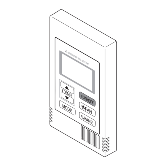
- Page 4 Component names and supplied parts The following parts are included in the box. Top case *1 Bottom case *2 Parts name Qty. Appearance Remote controller (top case) Right figure *1 Remote controller (bottom case) Right figure *2 Roundhead cross slot screws M4×30 Wood screw 4.1×16 (for direct wall installation) Installation Manual (this manual)
- Page 5 How To Wire Transmission Line The wiring is different when the remote controller is connected to a CITY MULTI control system (“-A” type and later) and when it is connected to a M-Series and P-Series air conditioner (A control type). The wiring also differs with the system configuration.
- Page 6 (4) To interlock to a LOSSNAY or OA processing unit, make the following settings using the remote controller. (For a description of how to set an interlock, see section Ventilation Setting Set the LOSSNAY or OA processing unit address and the address of all the indoor units you want to interlock.
- Page 7 (3) Up to two remote controllers can be connected to one group • When two remote controllers are connected to one group, always set the Main remote controller and Sub remote controller. • When only one remote controller is connected to one group, set it as the Main controller. When two remote controllers are connected to one group, set the Main remote controller and Sub remote controller.
- Page 8 • To monitor the accurate indoor temperature, install the remote controller away from direct sunlight, heat sources, and the supply air outlet of the air conditioner. • Install the remote controller in a location that allows the sensor to measure the representative room temperature.
- Page 9 3 Prepare the bottom case of the remote controller. Top case Bottom case 4 Connect the remote controller cable to the terminal block on the bottom case. Peel off the remote controller cable sheath as shown below to connect to the terminal block properly. Secure the remote controller cable so that the peeled part of the cable will fit into the case.
- Page 10 5 Install the bottom case. Be sure to secure two places of the bottom case. ■ Installation using a switch box ■ Direct wall installation Seal the cable Remote access hole controller cable Single switch box with putty. Wood Refer to 4. screws Refer to 1.
- Page 11 1 2 3 4 8 Connect the connector to the top case. Connect the connector on the bottom case to the socket on the top case. Connect the connector. Important To prevent malfunctions, do not remove the To prevent cable breakage and protective sheet or the circuit board from the malfunctions, do not hang the top controller top case.
- Page 12 ■ Direct wall installation (when running the cable along the wall) • Thread the cable through the access hole at the top of the remote controller. • Seal the cut-out part of the cover with putty. • Use a cable cover. Use a cable cover.
- Page 13 Test Run 1. Before making a test run, refer to the “Test Run” section of the indoor unit installation manual. 2. When the [ON/OFF] button and [TEMP. ] button are pressed simultaneously for 2 seconds or longer, test run is performed. 3.
- Page 14 - When LOSSNAY or OA processing unit are not registered 4 If registration is unnecessary, end registration by pressing and holding down the [ FAN] and [TEMP. ] buttons at the same time for two seconds. If a new LOSSNAY or OA processing unit must be registered, go to step 1. Registration procedure.
- Page 15 <2. Confirmation procedure> 8 Set the address of the indoor unit connected by the remote controller whose LOSSNAY or OA processing unit you want to confirm using the [TEMP. ] and [TEMP. ] buttons. (01 to 50) 9 Press the [ON/OFF] button and [ FAN] button simultaneously for 2 seconds, and check the LOSSNAY address registered at the set indoor unit address.
- Page 16 Function Selection for M-Series and P-Series Make the following settings for M-Series and P-Series if necessary. (This setting cannot be made with CITY MULTI Control System. To make CITY MULTI indoor unit settings from the remote controller, refer to section 9 Function Selection for CITY MULTI Set the functions of each indoor unit from the remote controller, as required.
- Page 17 [Function selection flow] First grasp the function selection flow. The following describes setting of “Thermistor selection” of Table 1 as an example. (For the actual setting procedure, see [Setting procedure] 1 to 0.) 1 Check the function selection set contents. 2 Switch to the FUNCTION SELECTION mode.
- Page 18 * If the remote controller enters the OFF state after the “ (FUNCTION)” and room temperature displays “ ” have flashes for two seconds, communication is probably abnormal. Make sure there are no noise sources near the transmission line. NOTE: If you make a mistake during operation, end function selection by step 0 and repeat selection from step 2.
- Page 19 6 Mode No. selection Select the mode No. you want to set with the B [TEMP. ] and C [TEMP. ] buttons. (Only the settable mode numbers can be selected.) Mode No. display Mode No. 02 = Thermistor selection 7 Select the setting contents of the selected mode. When the D [ FAN] button is pressed, the current setting No.
- Page 20 Function Selection for CITY MULTI Make this setting only when the function settings need to be changed on CITY MULTI. (This setting cannot be made with M-Series and P-Series Control System. To make settings for M-Series and P-Series, refer to section Function Selection for M-Series and P-Series Set the functions of each indoor unit from the remote controller, as required.
- Page 21 8If the set settings need to be changed, repeat steps 4 to 7. To complete the settings, press the [MODE] and the [ FAN] buttons at the same time for two seconds or longer. Response has been received. [TEMP. ] [TEMP. [MODE] [MODE] Indoor unit address setting...
- Page 22 5To check the settings, repeat steps 2 to 4. To complete the checking process, press the [MODE] and the [ FAN] buttons at the same time for two seconds or longer. Response has been received. [TEMP. ] [TEMP. [MODE] Indoor unit address setting Function Setting No.
- Page 23 3 Self-diagnosis result display <Error history> (For the contents of the error code, refer to the indoor unit installation manual or service handbook.) Error detection attribute Error code 4 digits or (Alternate error code 2 digits display) Address 3 digits or unit address No.
- Page 24 3 Remote controller check result <When remote controller is normal> Since there is no problem at the remote controller, check for other causes. <When remote controller is faulty> (Error display 1) “NG” flashes → Remote controller send/receive circuit abnormal Remote controller switching is necessary. When the problem is other than the checked remote controller (Error display 2) “E3”...
- Page 25 WT06429X01 Système de contrôle CITY MULTI et climatiseurs Mitsubishi séries M et P Contrôleur à distance simple MA PAC-YT53CRAU Manuel d’installation Pour distribution aux distributeurs et aux sous-traitants Ce manuel d'installation décrit comment installer le contrôleur à distance simple MA en vue de son utilisation avec le système de climatisation de bâtiment Mitsubishi, les unités intérieures de climatiseurs CITY MULTI de type extension directe (type «...
- Page 26 ATTENTION Pour prévenir tout risque d'endommager la télécommande, ne Évitez le contact avec les bords tranchants de certaines pulvérisez pas d'insecticide ou tout autre aérosol inflammable parties afin de prévenir tout risque de blessure et directement dessus. d'électrocution. Ne touchez pas l'écran tactile, les commutateurs ou les Pour prévenir tout risque de blessure, portez un équipement touches avec un objet pointu ou tranchant afin de prévenir de protection lors de toute intervention sur la télécommande.
- Page 27 Ne serrez pas trop les vis pour éviter d'endommager le contrôleur. Ce contrôleur est exclusivement destiné à être utilisé avec le Système de gestion d'immeuble de Mitsubishi Electric. Utilisez un tournevis à tête plate avec une lame de 5 mm L'utilisation de ce contrôleur avec d'autres systèmes ou à...
- Page 28 Nomenclature des composants et pièces fournies Les pièces suivantes sont incluses dans le coffret. Boîtier supérieur *1 Boîtier inférieur *2 Nomenclature Qté Apparence Contrôleur à distance (Boîtier supérieur) Figure de droite *1 Contrôleur à distance (Boîtier inférieur) Figure de droite *2 Vis à...
- Page 29 Comment brancher la ligne de transmission Le raccordement est différent lorsque le contrôleur à distance est connecté à un système de contrôle CITY MULTI (de type « –A » et versions ultérieures) et lorsqu’il est connecté à un climatiseur des séries M et P (de type de contrôle A).
- Page 30 (4) Pour interverrouiller un appareil LOSSNAY ou OA, effectuez les réglages suivants en utilisant le contrôleur à distance. (Pour l’interverrouillage, reportez-vous à la section 7 Réglage du ventilateur Réglez l’adresse de l’appareil LOSSNAY ou OA et celle de tous les autres appareils intérieurs que vous voulez interverrouiller.
- Page 31 (3) Il est possible de connecter jusqu’à deux contrôleurs à distance à un seul groupe • Lorsque deux contrôleurs à distance sont connectés à un seul groupe, définissez toujours un contrôleur à distance principal et un contrôleur à distance secondaire. •...
- Page 32 • Pour surveiller la température intérieure exacte, installez le contrôleur à distance à l'écart de la lumière directe du soleil, des sources de chaleur, et de la sortie d'air du climatiseur. • Installez le contrôleur à distance dans un endroit qui permette au capteur de mesurer une température représentative de celle de la pièce.
- Page 33 3 Préparez le boîtier inférieur du contrôleur à distance. Boîtier supérieur Boîtier inférieur 4 Connectez le câble du contrôleur à distance au bornier sur le boîtier inférieur. Dénudez la gaine du câble du contrôleur à distance comme illustré ci-après pour connecter correctement le bloc terminal.
- Page 34 5 Installez le boîtier inférieur. Veillez à fixer le boîtier inférieur en deux endroits. ■ Installation avec un boîtier de connexion ■ Installation directe sur le mur Câble du Bouchez le trou Boîtier de contrôleur à d'accès du câble connexion simple distance avec du mastic.
- Page 35 1 2 3 4 8 Reliez le connecteur au boîtier supérieur. Reliez le connecteur du boîtier inférieur à la prise du boîtier supérieur. Reliez le connecteur. Important Pour éviter des dysfonctionnements, ne Pour éviter une rupture du câble et des retirez pas le film de protection ou le circuit dysfonctionnements, ne laissez pas le imprimé...
- Page 36 ■ Installation directe sur le mur (quand on fait passer le câble le long du mur) • Enfilez le câble dans le trou d'accès en haut du contrôleur à distance. • Bouchez la partie évidée du couvercle avec du mastic. •...
- Page 37 Essai de fonctionnement 1. Avant d’effectuer un essai de fonctionnement, reportez-vous à la section “Essai de fonctionnement” du manuel d’installation de l’appareil intérieur. 2. Lorsque vous appuyez simultanément sur les boutons [ON/OFF] et [TEMP. ] pendant deux secondes ou plus, l’appareil effectue un essai de fonctionnement. 3.
- Page 38 - Lorsque l’appareil LOSSNAY ou OA n’est pas enregistré 4 Si l’enregistrement n’est pas nécessaire, terminez l’enregistrement en appuyant simultanément sur les boutons [ FAN] et [TEMP. ] et maintenez-les enfoncés pendant deux secondes. Si vous devez enregistrer un nouvel appareil LOSSNAY ou OA, reportez-vous à l’opération 1. Procédure d’enregistrement.
- Page 39 <2. Procédure de vérification> 8 Réglez l’adresse de l’appareil intérieur connecté via le contrôleur à distance dont vous souhaitez confirmer l’appareil LOSSNAY ou OA à l’aide des boutons [TEMP. ] et [TEMP. ]. (01 à 50) 9 Appuyez simultanément sur les boutons [ON/OFF] et [ FAN] pendant deux secondes, puis vérifiez l’adresse LOSSNAY enregistrée sur l’adresse de l’appareil intérieur programmé.
- Page 40 Sélection des fonctions des séries M et P Effectuez les réglages suivants pour les séries M et P, si nécessaire. (Vous ne pouvez pas effectuer ce réglage avec le système de contrôle CITY MULTI. Pour régler l'unité intérieure CITY MULTI à partir du contrôleur à distance, consultez la section 9 Sélection des fonctions du CITY MULTI Réglez les fonctions de chaque appareil intérieur à...
- Page 41 [Sélection des fonctions de la soufflerie] D’abord, saisissez la sélection des fonctions de la soufflerie. Ci-dessous se trouve la description du réglage de la “Sélection de la thermistance” du Tableau 1, à titre d’exemple. (Pour la procédure de réglage réelle, reportez-vous aux opérations 1 à 0: [Procédure de réglage.]) 1 Vérifiez le contenu des réglages de la sélection des fonctions.
- Page 42 * Si le contrôleur à distance se remet en position OFF après qu'il ait affiché, pendant deux secondes, “ (FONCTION)” et “ ” comme température de la pièce, la communication est probablement anormale. Vérifiez qu’il n’y a aucune source d’interférences à proximité de la ligne de transmission. REMARQUE : Si vous commettez une erreur pendant l’opération, terminez la sélection de la fonction comme indiqué...
- Page 43 6 Sélection du N° de mode Sélectionnez le N° de mode que vous désirez régler avec les boutons B [TEMP. ] et C [TEMP. ]. (Vous ne pouvez sélectionnez que les N° de mode réglables.) Affichage du N° du mode Mode N°...
- Page 44 Sélection des fonctions du CITY MULTI Effectuez ce réglage uniquement si les réglages de la fonction doivent être modifiés sur le CITY MULTI. (Ce réglage est impossible sur les systèmes de contrôle des séries M et P. Pour régler les séries M et P, consultez la section 8 Sélection des fonctions des séries M et P Réglez les fonctions de chaque unité...
- Page 45 8Si les réglages définis doivent être modifiés, répétez les étapes 4 à 7. Pour terminer les réglages, appuyez simultanément sur les boutons [MODE] et [ FAN] et maintenez-les enfoncés pendant au moins deux secondes. La réponse a été reçue. [TEMP. ] [TEMP.
- Page 46 5Pour vérifier les réglages, répétez les étapes 2 à 4. Pour terminer le processus de vérification, appuyez simultanément sur les boutons [MODE] et FAN] et maintenez-les enfoncés pendant au moins deux secondes. La réponse a été reçue. [TEMP. ] [TEMP. [MODE] Réglage de l'adresse de l'unité...
- Page 47 3 Affichage du résultat de la vérification automatique <Historique des erreurs> (Pour le contenu du code erreur, reportez-vous au manuel d’installation de l’appareil intérieur ou au manuel de service.) Attribut de détection d’erreur Code d’erreur à 4 (Affichage chiffres ou code alternatif) Adresse 3 chiffres ou N°...
- Page 48 3 Résultat de la vérification du contrôleur à distance <Lorsque le contrôleur à distance est normal> Si toutefois il n’y a pas de problème à le contrôleur à distance, vérifiez les autres causes possibles. <Lorsque le contrôleur à distance est défectueux> (Affichage d’erreur 1) “NG”...
Need help?
Do you have a question about the CITY MULTI PAC-YT53CRAU and is the answer not in the manual?
Questions and answers