Mitsubishi Electric CITY MULTI PAC-YT52CRA Installation Manual
Simple ma remote controller city multi control system and mitsubishi mr. slim air conditioners
Hide thumbs
Also See for CITY MULTI PAC-YT52CRA:
- Instruction manual (12 pages) ,
- Instruction book (12 pages) ,
- Installation manual (349 pages)
Table of Contents
Advertisement
CITY MULTI Control System
and Mitsubishi Mr. SLIM Air Conditioners
Simple MA Remote Controller
Installation Manual
This installation manual describes how to install the Simple MA Remote Controller for use with
Mitsubishi Building Air Conditioning System, direct expansion type CITY MULTI air conditioner indoor
units ("-A" type and later), and Mitsubishi Mr. SLIM packaged air conditioners.
Please be sure to read this installation manual and Instruction Book that are supplied with the Remote
Controller before proceeding with the installation. Failure to follow the instructions may result in
equipment damage.
For information on how to wire and install the air conditioning units, refer to the installation manual.
After the installation, hand over this manual to users.
1
Safety Precautions
• Read the following safety precautions prior to installation.
• Observe these precautions carefully to ensure safety.
WARNING
Indicates a risk of death or serious injury if you misuse the PAC-YT52CRA.
Indicates a risk of serious injury or structural damage if you misuse the
CAUTION
PAC-YT52CRA.
• After reading this manual, provide this manual to end user for future reference.
• Keep this manual for future reference and refer to it as necessary. This manual should be made
available to those who repair or relocate the controller. Make sure that the manual is forwarded to
future end users.
All electric work must be performed by qualified personnel.
General precautions
WARNING
Do not install the unit in a place where large amounts of
oil, steam, organic solvents, or corrosive gases, such
as sulfuric gas, are present or where acidic/alkaline
solutions or sprays are used frequently. These
substances can compromise the performance of the
unit or cause certain components of the unit to corrode,
which can result in electric shock, malfunctions,
smoke, or fire.
To reduce the risk of shorting, current leakage, electric
shock, malfunctions, smoke, or fire, do not wash the
controller with water or any other liquid.
To reduce the risk of electric shock, malfunctions,
smoke or fire, do not operate the switches/buttons or
touch other electrical parts with wet hands.
PAC-YT52CRA
For distribution to dealers and contractors
To reduce the risk of injury or electric shock, stop the
operation and switch off the power supply before
cleaning, maintaining, or inspecting the controller.
To reduce the risk of injury or electric shock, before
spraying a chemical around the controller, stop the
operation and cover the controller.
To reduce the risk of injury, keep children away while
installing, inspecting, or repairing the unit.
Properly install all required covers to keep moisture
and dust out of the controller. Dust accumulation and
water can cause electric shock, smoke, or fire.
– 1 –
WT06592X01
GB
Advertisement
Table of Contents

Related Manuals for Mitsubishi Electric CITY MULTI PAC-YT52CRA


Summary of Contents for Mitsubishi Electric CITY MULTI PAC-YT52CRA
-
Page 1: Safety Precautions
This installation manual describes how to install the Simple MA Remote Controller for use with Mitsubishi Building Air Conditioning System, direct expansion type CITY MULTI air conditioner indoor units (“-A” type and later), and Mitsubishi Mr. SLIM packaged air conditioners. -
Page 2: Precautions During Installation
CAUTION To reduce the risk of electric shock or malfunctions, do To reduce the risk of injury and electric shock, avoid not touch the touch panel, switches, or buttons with a contact with sharp edges of certain parts. pointy or sharp object. To reduce the risk of injury, wear protective gear when To reduce the risk of damage to the controller, do not working on the controller. -
Page 3: Additional Precautions
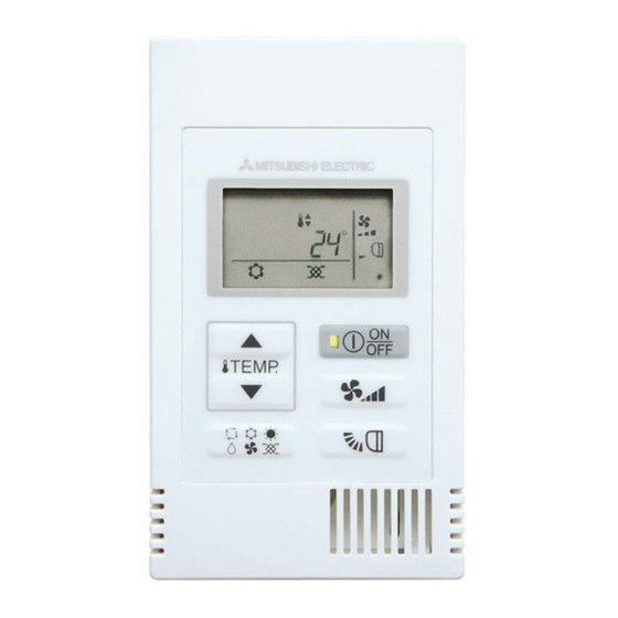
This controller is designed for exclusive use with the To avoid damage to the controller, do not overtighten Building Management System by Mitsubishi Electric. the screws. The use of this controller for with other systems or for Use a flat-head screwdriver with a blade width of 5 mm other purposes may cause malfunctions. - Page 4 Component names and supplied parts The following parts are included in the box. Top case *1 Bottom case *2 Parts name Qty. Appearance Remote controller (top case) Right figure *1 Remote controller (bottom case) Right figure *2 Roundhead cross slot screws M4×30 Wood screw 4.1×16 (for direct wall installation) Installation Manual (this manual)
- Page 5 How To Wire Transmission Line The wiring is different when the remote controller is connected to a CITY MULTI control system (“-A” type and later) and when it is connected to a Mr. SLIM air conditioner (A control type). The wiring also differs with the system configuration.
- Page 6 (4) To interlock to a LOSSNAY or OA processing unit, make the following settings using the remote controller. (For a description of how to set an interlock, see section Ventilation Setting Set the LOSSNAY or OA processing unit address and the address of all the indoor units you want to interlock.
-
Page 7: How To Install
(3) Up to two remote controllers can be connected to one group • When two remote controllers are connected to one group, always set the Main remote controller and Sub remote controller. • When only one remote controller is connected to one group, set it as the Main controller. When two remote controllers are connected to one group, set the Main remote controller and Sub remote controller. -
Page 8: Installation Space
• To monitor the accurate indoor temperature, install the remote controller away from direct sunlight, heat sources, and the supply air outlet of the air conditioner. • Install the remote controller in a location that allows the sensor to measure the representative room temperature. - Page 9 3 Prepare the bottom case of the remote controller. Top case Bottom case 4 Connect the remote controller cable to the terminal block on the bottom case. Peel off the remote controller cable sheath as shown below to connect to the terminal block properly. Secure the remote controller cable so that the peeled part of the cable will fit into the case.
- Page 10 5 Install the bottom case. Be sure to secure two places of the bottom case. ■ Installation using a switch box ■ Direct wall installation Seal the cable Remote access hole controller cable Single switch box with putty. Wood Refer to 4. screws Refer to 1.
- Page 11 1 2 3 4 8 Connect the connector to the top case. Connect the connector on the bottom case to the socket on the top case. Connect the connector. Important To prevent malfunctions, do not remove the To prevent cable breakage and protective sheet or the circuit board from the malfunctions, do not hang the top controller top case.
- Page 12 ■ Direct wall installation (when running the cable along the wall) • Thread the cable through the access hole at the top of the remote controller. • Seal the cut-out part of the cover with putty. • Use a cable cover. Use a cable cover.
-
Page 13: Ventilation Setting
Test Run 1. Before making a test run, refer to the “Test Run” section of the indoor unit installation manual. 2. When the button and button are pressed simultaneously for 2 seconds or longer, test run is performed. 3. Stop the test run by pressing the button. - Page 14 - When LOSSNAY or OA processing unit are not registered 4 If registration is unnecessary, end registration by pressing and holding down the buttons at the same time for two seconds. If a new LOSSNAY or OA processing unit must be registered, go to step 1. Registration procedure.
- Page 15 <2. Confirmation procedure> 8 Set the address of the indoor unit connected by the remote controller whose LOSSNAY or OA processing unit you want to confirm using the buttons. (01 to 50) 9 Press the button and button simultaneously for 2 seconds, and check the LOSSNAY address registered at the set indoor unit address.
- Page 16 Function Selection for Mr. SLIM Make the following settings for Mr. SLIM if necessary. (This setting cannot be made with CITY MULTI Control System. To make CITY MULTI indoor unit settings from the remote controller, refer to section 9 Function Selection for CITY MULTI Set the functions of each indoor unit from the remote controller, as required.
- Page 17 [Function selection flow] First grasp the function selection flow. The following describes setting of “Thermistor selection” of Table 1 as an example. (For the actual setting procedure, see [Setting procedure] 1 to 0.) 1 Check the function selection set contents. 2 Switch to the FUNCTION SELECTION mode.
- Page 18 * If the remote controller enters the OFF state after the “ (FUNCTION)” and room temperature displays “ ” have flashes for two seconds, communication is probably abnormal. Make sure there are no noise sources near the transmission line. NOTE: If you make a mistake during operation, end function selection by step 0 and repeat selection from step 2.
- Page 19 6 Mode No. selection Select the mode No. you want to set with the B and C buttons. (Only the settable mode numbers can be selected.) Mode No. display Mode No. 02 = Thermistor selection 7 Select the setting contents of the selected mode. When the D button is pressed, the current setting No.
- Page 20 Function Selection for CITY MULTI Make this setting only when the function settings need to be changed on CITY MULTI. (This setting cannot be made with Mr. SLIM Control System. To make settings for Mr. SLIM, refer to section Function Selection for Mr. SLIM Set the functions of each indoor unit from the remote controller, as required.
- Page 21 8If the set settings need to be changed, repeat steps 4 to 7. To complete the settings, press the and the buttons at the same time for two seconds or longer. Response has been received. Indoor unit address setting Function Setting No. setting Function Setting Value setting response Waiting for response...
-
Page 22: Self-Diagnosis
5To check the settings, repeat steps 2 to 4. To complete the checking process, press the and the buttons at the same time for two seconds or longer. Response has been received. Indoor unit address setting Function Setting No. setting response Waiting for response The specified indoor unit does not exist. -
Page 23: Remote Controller Check
3 Self-diagnosis result display <Error history> (For the contents of the error code, refer to the indoor unit installation manual or service handbook.) Error detection attribute Error code 4 digits or (Alternate error code 2 digits display) Address 3 digits or unit address No. - Page 24 HEAD OFFICE: TOKYO BLDG., 2-7-3, MARUNOUCHI, CHIYODA-KU, TOKYO 100-8310, JAPAN Authorized representative in EU: MITSUBISHI ELECTRIC EUROPE B.V. HARMAN HOUSE, 1 GEORGE STREET, UXBRIDGE, MIDDLESEX UB8 1QQ, U.K. – 24 –...
Need help?
Do you have a question about the CITY MULTI PAC-YT52CRA and is the answer not in the manual?
Questions and answers