
Related Manuals for Scotsman AF 80


Summary of Contents for Scotsman AF 80
- Page 1 Page 1 Page 1 SERVICE MANUAL AF 80 AF 100 AF 200 NEW PC BOARD VERSION R 134 A / R 404 A VERSIONS Electronic flakers with storage MS 1000.73 REV. 07/02...
-
Page 2: Table Of Contents
Page 2 Page 2 Table of contents page TABLE OF Specifications AF 80 CONTENTS Specifications AF 100 Specifications AF 200 GENERAL INFORMATION AND INSTALLATION Introduction Unpacking and Inspection Location and levelling Electrical connections Water supply and drain connections Final check list... -
Page 3: Specifications Af
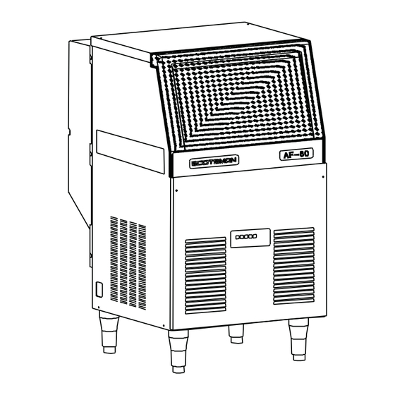
The daily ice-making capacity is directly related to the condenser air inlet temperature, water temperature and age of the machine. To keep your SCOTSMAN FLAKER at peak performance levels, periodic maintenance checks must be carried out as indicated on page 32 of this manual. - Page 4 Page 4 Page 4 SPECIFICATIONS Dimensions: HEIGHT (less legs) 813 mm. HEIGHT (with legs) 933 mm. WIDTH 535 mm. DEPTH 621 mm. WEIGHT 72 Kg. AF80 - MACHINE SPECIFICATIONS Ice bin Water req. Model Cond. unit Finish Comp. HP lt/24 HR AF80 AS 53** S.
- Page 5 NOTE. The daily ice-making capacity is directly related to the condenser air inlet temperature, water temperature and age of the machine. To keep your SCOTSMAN FLAKER at peak performance levels, periodic maintenance checks must be carried out as indicated on page 32 of this manual.
- Page 6 Page 6 Page 6 SPECIFICATIONS Dimensions: HEIGHT (less legs) 1006 mm. HEIGHT (with legs) 1126 mm. WIDTH 592 mm. DEPTH 622 mm. WEIGHT 72 Kg. AF100 - MACHINE SPECIFICATIONS Ice bin Water req. Model Cond. unit Finish Comp. HP lt/24 HR AF 100 AS 85** S.
- Page 7 NOTE. The daily ice-making capacity is directly related to the condenser air inlet temperature, water temperature and age of the machine. To keep your SCOTSMAN FLAKER at peak performance levels, periodic maintenance checks must be carried out as indicated on page 32 of this manual.
- Page 8 Page 8 Page 8 SPECIFICATIONS Dimensions: HEIGHT (less legs) 1006 mm. HEIGHT (with legs) 1126 mm. WIDTH 592 mm. DEPTH 622 mm. WEIGHT 72 Kg. AF 200 - MACHINE SPECIFICATIONS Ice bin Water req. Model Cond. unit Finish Comp. HP lt/24 HR AF 200 AS 100*...
-
Page 9: General Information And Installation
This manual provides the specifications and the step-by-step procedures for the installation, start- up and operation, maintenance and cleaning for CAUTION. Incorrect voltage supplied to the SCOTSMAN AF 80, AF 100 and AF 200 the icemaker will void your parts icemakers. replacement program. -
Page 10: Water Supply And Drain Connections
Page 10 Page 10 All SCOTSMAN ice machines are supplied from Connect the 3/4" GAS male fitting of the water the factory completely pre-wired and require only inlet, using the flexible hose supplied to the cold electrical power connections to the wire cord water supply line with regular plumbing fitting provided at the rear of the unit. -
Page 11: Installation Practice
12. Has the owner been given the name and the 10. Has the owner/user been given the User phone number of the authorized SCOTSMAN Manual and been instructed on the importance of Service Agency serving him? periodic maintenance checks? G. -
Page 12: Operating Instructions
Page 12 Page 12 OPERATING INSTRUCTIONS START UP B. Elapsed the 3 minutes - stand by period - the unit starts operating with the activation in sequence of the following assemblies: After having correctly installed the ice maker and completed the plumbing and electrical GEAR MOTOR connections, perform the following “Start-up”... - Page 13 Page 13 Page 13 FIG. 2 WATER LEVEL RESET GEAR MOTOR ROTATION CONTACTOR COIL RELAYS CONDENSER TEMP. T 40 ÷ ° EVAPORATOR TEMP. GEAR MOTOR ICE LEVEL CONTROL TRIAC FAN MOTOR TRANSF. ELECTRONIC CARD FIG. 3 WATER LEVEL RESET GEAR MOTOR ROTATION CONTACTOR COIL RELAYS...
-
Page 14: Operational Checks
Page 14 Page 14 NOTE. If, after ten minutes from the NOTE. On air cooled models, the condenser compressor start-up, the evaporating tem- temperature sensor, which is located within perature has not dropped down to a value the condenser fins, keep the head lower than -1 °... - Page 15 Page 15 Page 15 This will cause a gradual decrease of the water YELLOW LED goes off while the RED LED level in the float reservoir and as soon as the level starts blinking. gets below the sensors, the flaker stops to ope- After 3 minutes the unit resumes its total operation rate and the YELLOW warning LED will glow to with the immediate start-up of the gear motor...
- Page 16 Page 16 Page 16 NOTE. In the front of the PC Board is located NOTE. The ICE LEVEL CONTROL a small I/R Trimmer directly connected with (INFRA-RED SYSTEM) is independent of the optical Ice level control. By means of its the temperature however, the reliability of screw it is possible to modify the signal its detection can be affected by external...
-
Page 17: Principle Of Operation (How It Works)
Page 17 Page 17 PRINCIPLE OF OPERATION WATER CIRCUIT horizontal motion to be discharged out, through the ice spout, into the storage bin. The water enter in the machine through the water By running the ice maker, i.e. by putting the unit inlet fitting which incorporates a strainer and it is under power, starts the automatic and continuous located at the rear side of the cabinet and then it... - Page 18 Page 18 Page 18 the MICRO-PROCESSOR of the P.C. Board NOTE. In case the condenser temperature probe which energizes, through a TRIAC, the Fan s enses that the condenser temperature has Motor in ON-OFF mode. rised to 70 ° C (160 °...
-
Page 19: Mechanical System
MECHANICAL SYSTEM After having diagnosed and eliminated the source of the failure, to restart the unit it is The mechanical system of the SCOTSMAN Flaker necessary to switch OFF and ON the power machines consists basically of a gear motor line main disconnnect switch (Fig. -
Page 20: Operating Pressures
° (With 21 C ambient temperature) capillary tube REFRIGERANT CHARGE (R 134 A) air cooled water cooled Discharge pressure: AF 80 - 100 - 200 AF 80 310 gr 310 gr AF 100 420 gr xxxxx Air cooled version 8.5 ÷ 10 bar... -
Page 21: Components Description
Page 21 Page 21 start the unit operations up to the moment that COMPONENTS DESCRIPTION the ambient temperature will rise to more acceptables conditions (5°C). In the air cooled versions, in relation to the A. EVAPORATOR TEMPERATURE SENSOR different current received, the micro processor of The evaporator sensor probe is inserted into its the P.C. - Page 22 Page 22 Page 22 As soon as the ice is scooped out (with the YELLOW LED resumption of the light beam between the two Unit shut-off due to a infrared sensor of ice level control) 6 seconds later the too lo-water level into ice machine resumes its operation with the simul- float tank taneous extinguishing the 2nd YELLOW LED.
- Page 23 Page 23 Page 23 G. JUMPERS bearing is lubricated with a food grade - water resistant grease. The Flaker PC Board is equipped by three jumpers: NOTE. It is advisable to check the conditions J1 · TEST: Used in the factory to energise all of both the lubricant grease and the top the electrical components during the bearing every six months.
-
Page 24: Adjustment, Removal And Replacement Procedures
Page 24 Page 24 ADJUSTMENT, REMOVAL AND REPLACEMENT PROCEDURES B. REPLACEMENT OF EVAPORATOR NOTE. Read the instructions thoroughly TEMPERATURE SENSOR before performing any of the following adjustment or removal and replacement pro- Remove the front, rear and top panels. cedure. Remove the insulation from the refrigerant tubing, connecting the freezer to the accumulator, to gain access to the sensor probe well and be... -
Page 25: Replacement Of The Reservoir Water Level Sensor
Page 25 Page 25 Unloose the three screws securing the plastic To install the replacement spout follow cover to the gear motor speed sensor housing previous steps in reverse. and remove it. Unloose the two screws securing the sensor to the plastic housing and withdraw it from its REPLACEMENT OF THE AUGER, WATER seat. -
Page 26: Replacement Of The Gear Motor Assy
Remove front and back panel. bearings any time the auger is removed. To facilitate this, SCOTSMAN EUROPE Recover the refrigerant from the system and Service makes available a service Kit transfer it in a container so to reclaim or recycle P/N 001028.07 which includes besides the... -
Page 27: Replacement Of Air Cooled Condenser
Page 27 Page 27 Unsolder the refrigerant lines from the NOTE. It is imperative to install a replace- condenser and remove it from the unit. ment drier whenever the sealed refrigeration system is open. Do not replace the drier until all other repairs NOTE. -
Page 28: Replacement Of Compressor
Page 28 Page 28 Unsolder suction and process header from Q. REPLACEMENT OF COMPRESSOR compressor and retain it to be used on new compressor. Remove back and front panels. Remove the cover and disconnect the NOTE. It is imperative to install a replace- electrical leads from the compressor junction ment drier whenever the sealed refrigeration system is open. -
Page 29: Wiring Diagram
Page 29 Page 29 WIRING DIAGRAM AIR AND WATER COOLED GV - YELLOW GREEN 230/50/1 B - WHITE G - GREY N - BLACK A - BLUE M - BROWN V - GREEN... -
Page 30: Service Diagnosis
Page 30 Page 30 SERVICE DIAGNOSIS SYMPTON POSSIBLE CAUSE SUGGESTED CORRECTION Unit will not run Blown fuse in P.C.Board Replace fuse & check for cause of No LED lighted-up blown fuse Master switch in OFF position Turn switch to ON position Inoperative P.C.Board Replace P.C.Board Loose electrical connections... - Page 31 Page 31 Page 31 SERVICE DIAGNOSIS SYMPTON POSSIBLE CAUSE SUGGESTED CORRECTION Wet ice Ambinet temperature too high Move unit to cooler location High water level in the freezer Lower to approx. 20 mm below ice spout Faulty compressor Replace Machine runs but makes no ice Water not entering in the freezer Air look in feed line to freezer.
-
Page 32: Maintenance And Cleaning Instructions
If required, polish the two sensor rods secured to the float reservoir cover, heavy scale sediment on them can be removed with the help of a bit of SCOTSMAN Cleaner plain. C. CLEANING INSTRUCTIONS OF WATER With the ice machine and fan motor OFF on... - Page 33 Be sure none remains in the bin. SCOTSMAN Ice Machine Cleaner. 12. Pour into the water reservoir 1 cc. (approx 20 drops) of Scotsman Sanitiser (Antialgae P/N WARNING. The SCOTSMAN Ice Machine 264000.00) then switch the unit ON. Cleaner contains Phosphoric Hydroxyacetic acids.
Need help?
Do you have a question about the AF 80 and is the answer not in the manual?
Questions and answers