Advertisement
Quick Links
TROUBLESHOOTING
a
LED overview
LED
State
Description
Flashing red in unison
The IQ Gateway Metered is booting up
All
Flashing green sequentially Software upgrade in progress
Solid green
Communicating with Enphase Installer App
Flashing green
WPS connection in progress or the IQ
Gateway Metered is attempting to connect
Network
to Enphase Installer App
communica-
tions
Solid red
Local network connection only
Off
No network connection
Solid green
AP mode enabled:
IQ Gateway Metered Wi-Fi network available
Off
AP mode disabled:
AP mode
IQ Gateway Metered Wi-Fi network unavail-
able
Solid green
All communicating microinverters are
producing
Flashing green
Microinverter upgrade in progress
Power
Solid red
At least one microinverter is not producing
production
Off
Microinverters are not producing or com-
municating (low light or night time)
Solid green
All devices are communicating
Flashing green
Device scan in progress
Device
Solid red
At least one device is not communicating
communica-
tions
Off
Devices are not communicating
(low-light or nighttime)
b
Device detection issues
If the Device Communications LED
lights solid red, it may result from low-light
levels. If there is insufficient sunlight to power up the microinverters, they cannot
communicate with the IQ Gateway.
If there is sufficient daylight for the microinverters to power up, the issue may be that
the IQ Gateway Metered is having difficulty in communicating over the power lines. To
troubleshoot this issue:
Check the Enphase Installer App to see which devices are not
•
communicating.
Check that the PV array's circuit breaker(s) are in the "ON" position.
•
Verify that the PV modules are connected to the microinverters.
•
Verify that the PV module DC voltage is within the allowable range for the microin-
•
verter.
c
Power production issues
If the Power Production LED
lights solid red, check the Enphase Installer App to see
which microinverters are not producing power.
If none of the microinverters are producing power, there may be a grid or wiring
•
issue. First, verify the proper input voltage and frequency from the grid. Next,
check the breaker and wiring, starting at the switchboard.
•
If all of the non-productive microinverters are on the same branch, check the
breaker and wiring starting at the junction box for the affected branch.
If only one or scattered microinverters are not producing power, check to see that
•
the AC connectors are fully seated in the engage cable connectors. Next, check
that each module provides the required startup voltage for the microinverter
(22 V). A PV module that is failing or that is undersized may not generate enough
power for AC conversion.
Internet connection issues
d
If you are using Wi-Fi and the Network Communications LED
remains off:
•
The WPS connection window may have timed out. Retry the connection steps.
Ensure the broadband router is operational by checking that other devices at the
•
site can access the network.
Be aware that metal enclosures or obstructions impede wireless communication.
•
If you cannot see your router or access point in the list on the IQ Gateway, or
•
cannot maintain a connection, it may be necessary to add a wireless repeater to
extend the network range.
If you are using Wi-Fi and the Network Communications LED lights solid red, ensure
the broadband router is connected to the Internet by checking that other devices at the
site can access the Internet.
If you are using the Enphase Mobile Connect modem and the Network Communica-
tions LED remains off or lights solid red, see Troubleshooting in the
Enphase Mobile
Connect Installation
Guide.
For any connection method, you can troubleshoot network issues with the Enphase
Installer App by tapping the "Network" button, then "Diagnostic Tools".
If you replace the broadband router, configure the IQ Gateway Metered Wi-Fi settings
for the new Wireless Network Name (SSID) and password.
Enphase Support:
http://www.enphase.com/global/contact/
SAFETY
Safety and advisory symbols
DANGER: This indicates a hazardous situation, which if not avoided,
will result in death or serious injury.
⚠
WARNING: This indicates a situation where failure to follow instruc-
tions may be a safety hazard or cause equipment malfunction. Use
extreme caution and follow instructions carefully.
✓
NOTE: This indicates information particularly important for optimal
system operation. Follow instructions carefully.
Safety instructions
DANGER: Risk of electric shock. Risk of fire. Do not attempt to repair
the IQ Gateway Metered; it contains no user-serviceable parts.
Tampering with or opening the IQ Gateway Metered will void the
warranty. Warranty void if cover removed. If the IQ Gateway Metered
fails, contact Enphase customer support for assistance
http://enphase.com/philippines
.
DANGER: Risk of electrocution! Do not install CTs when current is
flowing in the sensed circuit. Always install CT wires in the terminal
blocks before energising the sensed circuit.
DANGER: Risk of electric shock. Do not use Enphase equipment in a
manner not specified by the manufacturer. Doing so may cause death
or injury to persons, or damage to equipment.
DANGER: Risk of electric shock. Be aware that installation of this
equipment includes risk of electric shock. If you wire the IQ Gateway
Metered at the sub-board, always de-energise the sub-board before
beginning.
DANGER: Risk of electric shock. Risk of fire. Only qualified personnel
should troubleshoot, install, or replace the IQ Gateway Metered.
DANGER: Risk of electric shock. Risk of fire. Do not wire unused termi-
nals or terminal blocks on the IQ Gateway Metered..
⚠
WARNING: Before installing or using the IQ Gateway Metered, read all
instructions and cautionary markings in the technical description and
on the IQ Gateway Metered.
⚠
WARNING: Risk of equipment damage. If installing the IQ Gateway
Metered in an enclosure, choose an area for installation where the
ambient temperature does not exceed 46ºC.
✓
NOTE: Do not install the CTs in a panel where they exceed 75% of the
wiring space of any cross-sectional area within the panel, or refer to
local standards for guidance.
✓
NOTE: Perform all electrical installations by all national and local
electrical codes.
✓
NOTE: To ensure optimal reliability and to meet warranty require-
ments, the IQ Gateway Metered must be installed according to the
instructions in this guide.
© 2023 Enphase Energy. All rights reserved. Enphase,
the e and CC logos, IQ, and certain other marks listed at
https://enphase.com/trademark-usage-guidelines
are
trademarks of Enphase Energy, Inc. in the US and other
countries. Data subject to change. Rev04/2023-08-25
Q U I C K I N S T A L L G U I D E - P H I L I P P I N E S
Installing the IQ Gateway Metered
To install the IQ Gateway Metered, read and follow all warnings and instructions in this guide. Safety warnings are listed at the end
of this guide.
How it works
Enphase Installer App
Microinverters
IQ Gateway
Metered
Switchboard
Router
To internet
Powerline
Network
Communications
Communications
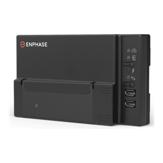
IQ Gateway Metered display and controls
Track system installation progress with the Enphase Installer App mobile
app. The LEDs on the IQ Gateway Metered are solid green when a function
is enabled or performing as expected, flashing when an operation is in
progress, or solid red when troubleshooting with Enphase Installer App is
required. For a legend of all LED states, see Troubleshooting
a
.
Network communications LED
Green when IQ Gateway Metered is
connected to Enphase Installer App.
AP mode LED
Green when IQ Gateway AP Wi-Fi
network is available.
AP mode button
Press to enable IQ Gateway AP mode
for connecting with a mobile device.
Hold for 5-seconds to start WPS
connection to a router.
Power production LED
Green when microinverters are
Enphase Installer
producing power.
App
Device communications LED
Green when devices are
communicating with IQ Gateway Metered.
Device scan button
Press to start/stop 15minute scan for
devices over the power line.
(Model ENV-S-AM1-230-60)
PREPARATION
A ) Download the latest version of the Enphase Installer App
and open it to log in to your Enphase Installer App
account. This mobile app lets you connect to the
IQ Gateway Metered to track system installation prog-
ress. To download, go to
enphase.com/installerapp
or
scan the QR code on the right.
B ) Check the box for the following items:
IQ Gateway Metered
•
Two split-core Current Transformers (CTs) for production and
•
consumption metering
DIN rail for mounting the IQ Gateway Metered
•
Quick Install Guide (this document)
•
Anatel logo and warning labels
•
C ) Make sure there is enough space in the switchboard to install CTs.
Do not install the CTs in a panel where they exceed 75% of the wiring
space of any cross-sectional area within the panel.
D ) Install the IQ Gateway Metered in an IP54-rated or better enclosure
with conduit attachment when installing outdoors. Do not drill
holes on the top of the enclosure or anywhere that allows moisture
ingress. Metallic enclosures may impair Wi-Fi signal strength. Use
an appropriately rated enclosure if installing the IQ Gateway Metered
indoors.
E ) If you are installing the IQ Gateway Metered in a multi-phase applica-
tion, make sure you have the following items:
• Additional CTs (CT-100-SPLIT) for multi-phase installations.
Ensure you have one CT for each phase monitored for both pro-
duction and consumption.
• A phase coupler. If installing on a three-phase site, install a phase
coupler on the load side of the overcurrent protection device. See
your region's technical brief on phase coupling at
enphase.com/
support. Consult Enphase support for compatible devices.
F ) Decide how to connect the IQ Gateway Metered to the Internet:
choose Wi-Fi, an Enphase Mobile Connect modem, or Ethernet.
G ) Ensure to have the following optional items, if needed:
Enphase Mobile Connect™ modem (order CELLMODEM-02)
•
Ethernet over power line communication (PLC) bridge with Ether-
•
net cables [order EPLC-02 (EU), EPLC-03 (UK) or EPLC-04 (AU/NZ)]
Ethernet cable [802.3, Cat5E or Cat6, unshielded twisted pair
•
(UTP)]. Do not use shielded twisted pair (STP) cable.
H ) Install the PV system as directed by the installation manuals.
I ) If an Enphase PV system is or will be installed at the site, create a
paper installation map to record device serial numbers and positions
in the array. You will scan this map later using Enphase Installer App
and your mobile device.
Peel the removable label from the bottom of the IQ Gateway Me-
•
tered, and affix it to the paper installation map.
Always keep a copy of the installation map for your records.
•
For installation in Brazil, apply the Anatel logo label and warning
•
label on to the IQ Gateway surface at a visible location. These
labels are provided with this box.
NOTE: If needed, you can find an installation map with any
Microinverter Quick Install
Guide.
For three-phase systems, use an external disconnect device for
managing loss of phase (LOP) requirements.
Enphase
Advertisement

Subscribe to Our Youtube Channel
Related Manuals for enphase ENV-S-AM1-230-60


Summary of Contents for enphase ENV-S-AM1-230-60
- Page 1 AC conversion. network is available. H ) Install the PV system as directed by the installation manuals. I ) If an Enphase PV system is or will be installed at the site, create a AP mode button Internet connection issues...
- Page 2 A ) On your mobile device, go to Settings and disconnect from the wiring. C ) If the “IQ Gateway” and “Enphase Cloud (or the cloud icon)” are not IQ Gateway’s Wi-Fi network. doors, install the IQ Gateway Metered in an IP54-rated, or better, Make sure supply wiring is 2.5 mm...
- Page 3 Consumption DRED bypass DRM port © 2023 Enphase Energy. All rights reserved. Enphase, the e and CC logos, IQ, and certain other marks listed at https://enphase.com/trademark-usage-guidelines are trademarks of Enphase Energy, Inc. in the US and other countries. Data subject to change.
Need help?
Do you have a question about the ENV-S-AM1-230-60 and is the answer not in the manual?
Questions and answers