Table of Contents
Advertisement
Quick Links
One Technology Way • P.O. Box 9106 • Norwood, MA 02062-9106, U.S.A. • Tel: 781.329.4700 • Fax: 781.461.3113 • www.analog.com
Evaluating the
FEATURES
Full featured evaluation board for the
Easy connection to test equipment
Thru line for calibration
EQUIPMENT NEEDED
DC power supply
Signal generator
Spectrum analyzer
Network analyzer
PLEASE SEE THE LAST PAGE FOR AN IMPORTANT
WARNING AND LEGAL TERMS AND CONDITIONS.
ADRF5515
Dual-Channel, 3.3 GHz to 4.0 GHz, Receiver Front End
ADRF5515
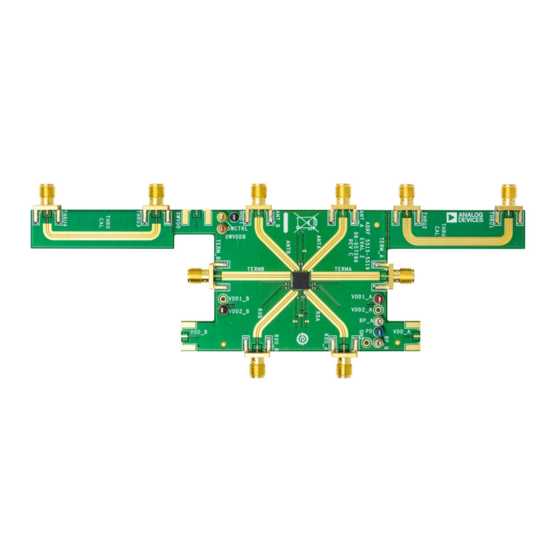
EVALUATION BOARD PHOTOGRAPH
ADRF5515-EVALZ
GENERAL DESCRIPTION
The
ADRF5515
end ideally suited for time division duplexing (TDD) wireless
infrastructure applications. The
power switch and a two-stage low noise amplifier (LNA) on
each channel.
This user guide describes the ADRF5515-EVALZ evaluation
board, designed to easily evaluate the features and performance
of the ADRF5515. A photograph of the evaluation board is
shown in Figure 1.
The
ADRF5515
ADRF5515. Consult the
with this user guide when using the evaluation board.
Figure 1.
Rev. 0 | Page 1 of 9
User Guide
is an integrated, dual-channel receiver front
ADRF5515
consists of a high
data sheet provides full specifications for the
ADRF5515
data sheet in conjunction
UG-1762
Advertisement
Table of Contents

Related Manuals for Analog Devices ADRF5515

Summary of Contents for Analog Devices ADRF5515
-
Page 1: Features
This user guide describes the ADRF5515-EVALZ evaluation Signal generator board, designed to easily evaluate the features and performance Spectrum analyzer of the ADRF5515. A photograph of the evaluation board is Network analyzer shown in Figure 1. ADRF5515 data sheet provides full specifications for the ADRF5515. -
Page 2: Table Of Contents
UG-1762 ADRF5515-EVALZ User Guide TABLE OF CONTENTS Features ....................1 Power Supply Inputs ..............3 Equipment Needed ................1 Control Inputs ................4 General Description ................. 1 RF Inputs and Outputs ..............4 Evaluation Board Photograph ............1 Test Procedure ...................5 Revision History ................2 Evaluation Board Schematic and Artwork ........7... -
Page 3: Evaluation Board Hardware
Ground via fences are arranged on both sides of a CPWG to G = 13mil improve isolation between nearby RF lines and other signal lines. W = 18mil The exposed ground pad of the ADRF5515, which is soldered on 2oz Cu (2.7mil) 2oz Cu (2.7mil) 2oz Cu (2.7mil) T = 2.7mil... -
Page 4: Control Inputs
By default, the evaluation board comes assembled and shipped without SMA connectors and series components on the thru The ADRF5515-EVALZ evaluation board has four control lines. To measure and calibrate out the board loss effects, the inputs, described in Table 2. Each control input is decoupled user must connect these connectors and components. -
Page 5: Test Procedure
Turn on the 5 V supply that sources a current of have sufficient power handling. approximately 180 mA. The ADRF5515-EVALZ features a support plate attached to the Turn on the RF signal generator. The spectrum analyzer bottom side of the board. To ensure maximum heat dissipation displays a tone of approximately 3 dBm at 3.3 GHz so that... - Page 6 UG-1762 ADRF5515-EVALZ User Guide 5V POWER SUPPLY UNIT 50Ω LOAD CONNECT TO SUPPLY, CONTROL AND GROUND TEST POINTS SPECTRUM GENERATOR SIGNAL GENERATOR CENTER = 3.6GHz SPAN = 1MHz ATTENUATION = 20dB REFERENCE LEVEL = +10dB RESOLUTION BANDWIDTH = 30kHz FREQUENCY = 3.6GHz POWER = –30dBm...
-
Page 7: Evaluation Board Schematic And Artwork
ADRF5515-EVALZ User Guide UG-1762 EVALUATION BOARD SCHEMATIC AND ARTWORK VDD_A 142-0701-851 AGND VDD2_CHA 0Ω VDD2_A VDD2_CHA VDD1_A VDD1_CHA GND1 10µF 1000pF 10µF 1000pF AGND AGND TERM_CHA TERM_A AGND 142-0701-851 AGND RXO_A 142-0701-851 100pF AGND RXOUT_CHA RXOUT_CHA ANT_A ANT_CHA ANT_CHA 142-0701-851... - Page 8 UG-1762 ADRF5515-EVALZ User Guide Figure 5. Evaluation Board Assembly Diagram Rev. 0 | Page 8 of 9...
-
Page 9: Ordering Information
By using the evaluation board discussed herein (together with any tools, components documentation or support materials, the “Evaluation Board”), you are agreeing to be bound by the terms and conditions set forth below (“Agreement”) unless you have purchased the Evaluation Board, in which case the Analog Devices Standard Terms and Conditions of Sale shall govern. Do not use the Evaluation Board until you have read and agreed to the Agreement.
Need help?
Do you have a question about the ADRF5515 and is the answer not in the manual?
Questions and answers