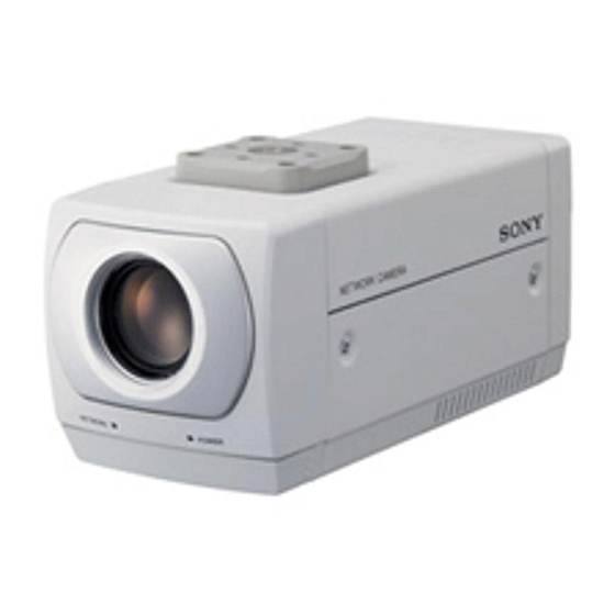
Sony IPELA SNC-Z20N User Manual
Sony snc-z20n: user guide
Hide thumbs
Also See for IPELA SNC-Z20N:
- Installation manual (104 pages) ,
- Service manual (62 pages) ,
- Specifications (6 pages)

Related Manuals for Sony IPELA SNC-Z20N


Summary of Contents for Sony IPELA SNC-Z20N
-
Page 1: Network Camera
3-796-928-14 (2) Network Camera User’s Guide Software Version 1.0 SNC-Z20N/Z20P © 2003 Sony Corporation... -
Page 2: Table Of Contents
Table of Contents Overview Phenomena Specific to CCD Image Sensors ... 5 How to Use This User’s Guide ... 5 Operating the Camera Logging in to Homepage — Welcome Page ... 6 Logging in as a User ... 6 Logging in as Administrator ... 6 About Viewers ... - Page 3 Setting the Activity Detection Area ... 41 Showing the Pop-up — Pop-up setting Page ... 42 Others Using the Supplied Setup Program ... 43 Assigning the IP Address Using the Setup Program ... 43 Changing the Communication Bandwidth ... 45 Setting the Date and Time ...
-
Page 4: Overview
EITHER DURING THE WARRANTY PERIOD OR AFTER EXPIRATION OF THE WARRANTY, OR FOR ANY OTHER REASON WHATSOEVER. • If you lose data by using this unit, SONY accepts no responsibility for restoration of the data. NOTICE TO USERS © 2003 Sony Corporation. All rights reserved. This... -
Page 5: Phenomena Specific To Ccd Image Sensors
Phenomena Specific to CCD Image Sensors The following phenomena that may appear in images are specific to CCD (Charge Coupled Device) image sensors. They do not indicate malfunctions. White flecks Although the CCD image sensors are produced with high-precision technologies, fine white flecks may be generated on the screen in rare cases, caused by cosmic rays, etc. -
Page 6: Operating The Camera
Operating the Camera The Operating the Camera section explains how to monitor the image from the camera using the Web browser. Use Internet Explorer as the Web browser. For setting the camera, see “Administrating the Camera” on page 13. Logging in to Homepage —... -
Page 7: About Viewers
The welcome page is changed to that for Administrator. Select the viewer. You can select the viewer from among Java applet viewer, ActiveX viewer whichever is suitable for your system environments and usage. For details, see “About Viewers” on page 7. When you have selected the viewer, the main viewer page appears (see page 8). -
Page 8: Configuration Of Main Viewer Page
Configuration of Main Viewer Page When you select the viewer, the main viewer page is displayed. This section briefly explains the functions of the parts and controls on the main viewer page. For a detailed explanation on each part or control, see the specified pages. -
Page 9: Monitor Image Section
View size Selects the image size to be displayed. See “Selecting the view size” on page 9. Camera control parts These parts are displayed when you click Control on the menu section. You can operate the camera using these parts. See “Operating the Camera from the Image Control Section”... -
Page 10: Operating The Camera From The Image Control Section
Operating the Camera from the Image Control Section You can operate the camera from the image control section on the main viewer page. For this function, user access right Level 2 to Level 4 is required (see page 25). Click Control on the menu section to display the camera control parts. -
Page 11: Operating The Camera From The Monitor Image
Operating the Camera from the Monitor Image You can operate zooming of the camera by clicking the mouse on the monitor image. Zooming is also operative using the zoom bar under the monitor image. For this function, user access right Level 2 to Level 4 is required (see page 26). -
Page 12: Recording A Still Image On An Ata Memory Card Or The Built-In Memory Of The Camera
Recording a Still Image on an ATA Memory Card or the Built-in Memory of the Camera If you select Memory save and click still image is captured and stored in the memory specified on the Image memory setting page. To use this function, you need to select the Use image memory function option and the Manual mode on the Image memory setting page. -
Page 13: Administrating The Camera
Administrating the Camera The Administrating the Camera section explains how to set the functions of the camera by the Administrator. For monitoring the camera image, see “Operating the Camera” on page 6. Configuration of Administrator Menu Page The Administrator menu page is displayed when the Administrator having Level 4 access right selects Setting on the welcome page for Administrator, or when Setting button on the menu section of the main... -
Page 14: Configuring The System - System Setting
Schedule Displays the Schedule setting page. See “Setting the Schedule — Schedule setting Page” on page 40. Activity detection Displays the Activity detection setting page. See “Setting the Activity Detection Function — Activity detection setting Page” on page 41. Pop-up Displays the Pop-up setting page. -
Page 15: System Log
/ddrv/ from the drop-down list when using the built-in flash memory. Type the path of the homepage in the text box up to 64 characters. For the verified cards, contact your authorized Sony dealer. A-slot (adrv) Displays the type of the PC card inserted into the PC card slot and its free card space. -
Page 16: Date Time Setting Section
Date time setting Section Current date time Displays the date and time set on the camera. You can set the date and time using the following two methods. Note When you purchased the camera, be sure to check the date and time of the camera and set them if necessary. System (PC) current date time Displays the date and time set on your computer. -
Page 17: Initialization Section
Initialization Section Backup setting Saves the setting data of the camera in a file. Click Save, and follow the instructions on the browser to specify the folder and save the setting data of the camera. The file name preset at the factory is “snc- z20.cfg.”... -
Page 18: Image Quality
Image quality Select the image quality from Level 1 to Level 10. A higher level gives a higher image quality, but the frame rate decreases as the data size increases. The following table shows the relation between the data size of a 24-bit image (8 bits for each R, G and B), and the compression rate for each Level setting. -
Page 19: Exposure Mode
The trimming portion is determined as shown below: Point rotated by 180° around the axis of the center of the still image Still image Red trimming Center of the frame still image To change the trimming portion, click on another point on the image. -
Page 20: Day/Night Setting Section
Note When the shutter speed is set to 1 sec or 1/2 sec in the Shutter priority or Manual mode, set the Focus mode menu and the White balance mode menu to Manual. Exposure compensation When the Exposure mode menu is set to Full auto, Shutter priority or Iris priority, select On to activate the exposure compensation, or Off to deactivate it. -
Page 21: Camera Control Mode Setting Section
Camera control mode setting Section You can set the operation mode for zooming using the TELE and WIDE buttons (see page 10), and for manual focusing using the NEAR and FAR buttons (see page 10). Mode Select the operation mode of the mouse. Normal: When you click the mouse button, the camera starts zooming operation, or the focus adjustment starts, and the operation/adjustment continues while... -
Page 22: Wireless Lan Setting Section
Verified wireless LAN adapter card Cisco Aironet 350 Series Client Adapter: AIR-PCM352 For details on the wireless LAN card, consult your authorized Sony dealer or the store where you purchased the product. Configuring the Network — Network setting Page DHCP Select On to assign the IP address to the camera automatically. -
Page 23: Http Port Setting Section
Bandwidth control Limits the data communication bandwidth for the wireless interface of the camera. You can select from among the following: Unlimited, 0.5, 0.6, 0.7, 0.8, 0.9, 1.0, 2.0, 3.0 (Mbps) Select Unlimited when you do not want to limit the bandwidth. -
Page 24: Notifying The Ip Address - Dynamic Ip Address Notification Section
Notifying the IP Address — Dynamic IP address notification Section When the DHCP menu is set to On, you can send the notification of the completion of the network settings (Wired LAN settings and Wireless LAN settings) using the SMTP or HTTP protocol. SMTP Select On to send an E-mail when the DHCP setting is completed. -
Page 25: Setting The User - User Setting Page
<MACADDRESS> Use this tag to embed the MAC address of the interface which IP address you have acquired by the DHCP, in the text or parameter. <MODELNAME> Use this tag to embed the camera's model name (SNC- Z20N or SNC-Z20P) in the text or parameter. <SERIAL>... -
Page 26: Setting The Security - Security Setting Page
Access right Select the access right for each user from the drop-down list. You can select from Level 1 to Level 4. The rights afforded to each access right are as follows: Level 1: Allows monitoring of the camera image (including some operations for monitoring). -
Page 27: Sending Images To Ftp Server
Network address/Subnet 1 to Network address/Subnet 10 Type the IP addresses and subnet mask values you want to allow or deny access to the camera. You can specify up to 10 IP addresses and subnet mask values. For a subnet mask, type 8 to 32. To temporarily cancel the Default Policy for a specified IP address/subnet mask, select Allow or Deny from the drop-down list on the right. -
Page 28: Alarm Mode Setting Section
FTP server name Type the FTP server name to upload still images up to 64 characters, or the IP address of the FTP server. User name Type the user name for the FTP server. Password Type the password for the FTP server. Re-type password To confirm the password, type the same characters as you typed in the Password box. -
Page 29: Periodical Sending Mode Setting Section
Available period Select the period for which the selected alarm mode is available. Always: The selected alarm mode is available any time. Use scheduler: The selected alarm mode is available according to the schedule selected in Schedule No. below. Schedule No. When Use scheduler is selected on the Available period menu, select the schedule you want the selected alarm mode being available. -
Page 30: Operating The Digest Viewer
Note The actual interval may be longer than the set value depending on image size and the network environments. Built-in memory Displays the built-in memory space. Click View to display the Backup FTP log page to show network failures and event information. Click Clear to delete the log contents. -
Page 31: Downloading Images From The Camera
Downloading Images from the Camera — FTP server setting Page When you click FTP server on the Administrator menu, the FTP server setting page appears. Use this page to set up for the FTP server function which finds a specified still image file stored in the built-in memory of the camera (about 8 MB) or the ATA memory card inserted into the PC card slot, or download the still image file from the card. -
Page 32: Sending An Image Via E-Mail - Smtp Setting Page
Sending an Image via E- mail — SMTP setting Page When you click SMTP on the Administrator menu, the SMTP setting page appears. Use this page to set up for the SMTP function that can capture and send a still image attached to an E-mail. You can capture a still image at the moment when a trigger occurs by an external sensor input, the built-in activity detection function or a manual trigger button. -
Page 33: Alarm Mode Setting Section
Mode Select the mode of the SMTP function. Manual: Sends a still image attached to an E-mail manually. After selecting Manual, click OK. The SMTP function mode is set to Manual. In this mode, when you click the button on the main viewer page, a still image is captured and sent via an E-mail. -
Page 34: Alarm Out 1 Or 2 Setting Page
Setting the Alarm Out 1 or 2 — Alarm out 1 or 2 setting Page When you click Alarm out 1 on the Administrator menu, the Alarm out 1 setting page appears. When you click Alarm out 2 on the Administrator menu, the Alarm out 2 setting page appears. -
Page 35: Timer Mode Setting Section
The recorded image file can be found or downloaded to the computer using the FTP server function. (See “Downloading Images from the Camera — FTP server setting Page” on page 31.) For the verified cards, contact your authorized Sony dealer. Activating/Deactivating the Image Memory Function — Image memory... -
Page 36: Recording An Image In The Selected Memory - Image Memory Setting Page
Memory Select the memory you want to store the image to, from the drop-down list. Built-in memory: Built-in memory of the camera (about 8 MB) ATA memory card: ATA memory card inserted into PC card slot of the camera Notes •... -
Page 37: Alarm Mode Setting Section
Alarm: Records a still image in the selected memory by synchronizing with an external sensor input or the built-in activity detection function. When you select Alarm, the Alarm mode setting section appears (see page 37). Note If the Suffix menu is set to None, you cannot select the Alarm mode. -
Page 38: Directory Structure Of Image Memory
Click to select the check box(es) 1 to 6. You can select multiple schedules. To check the contents of schedules, click Schedule check. (See “Setting the Schedule — Schedule setting Page” on page 40.) Digest viewer If you select On, an HTML file (.html) and a Java Script file (.js) are added every 100 files. -
Page 39: Setting The Alarm Buffer
DOS command “telnet [host name] [assigned port number]”. VISCA: When you select VISCA, you can control the camera using the VISCA protocol. For the command list of the VISCA protocol, consult your authorized Sony dealer. -
Page 40: Setting The Schedule - Schedule Setting Page
Notes • When you control the camera via the serial port using the VISCA protocol, match the communication settings with those on the connected controller. • This camera does not support the daisy chain connection of VISCA devices. Connect the camera and the controller one for one. -
Page 41: Setting The Activity Detection Function
Setting the Activity Detection Function Activity detection setting Page When you click Activity detection on the Administrator menu, the Activity detection setting page appears. Use this page to set up for the activity detection to link various applications. Sensitivity Select the sensitivity of the activity detection from the drop-down list. -
Page 42: Showing The Pop-Up - Pop-Up Setting Page
Showing the Pop-up — Pop-up setting Page When you click Pop-up on the Administrator menu, the Pop-up setting page appears. Use this page to set up for displaying a pop-up with your favorite message on the computers monitoring the camera image, or for displaying a pop-up automatically when there is an alarm input. -
Page 43: Others
Others Using the Supplied Setup Program To connect the camera to a network, you need to assign a new IP address to the camera when you installed the camera for the first time. You can assign an IP address in two ways: •... - Page 44 Set the IP address. To obtain the IP address automatically from a DHCP server: Select Obtain an IP address automatically. The IP address, Subnet mask and Default gateway are assigned automatically. To specify the IP address manually: Select Use the following IP address, and type the IP address, Subnet mask and Default gateway in each box.
-
Page 45: Changing The Communication Bandwidth
Changing the Communication Bandwidth Click the Bandwidth control tab to display the bandwidth setting window. The current bandwidth is displayed in Current bandwidth. Click to select the desired bandwidth from the Setting bandwidth list box. Type the Administrator name and Administrator password in each box. -
Page 46: Assigning The Ip Address To The Camera Using Arp Commands
Assigning the IP Address to the Camera Using ARP Commands This section explains how to assign an IP address to the camera using ARP (Address Resolution Protocol) commands without using the supplied setup program. Note When you turn on the camera, execute the ARP and PING commands within 5 minutes. -
Page 47: Using The Snmp
(standard format) With the above inquiry, you can obtain the following setting information. The following explains the setting information using the inqjs=snmp (JavaScript parameter) format. var sysDescr=“\“SONY Network Camera SNC- RZ30\”” var sysObjectID=“1.3.6.1.4.1.122.8501” var sysLocation=“\“\”” var sysContact=“\“\”” var sysName=“\“\””... - Page 48 the <string> position. The maximum length of <string> is 255 characters. sysName=<string> Set the instance of “mib-2.system.sysName.0” in the <string> position. The maximum length of <string> is 255 characters. enaAuthTraps=<value> Set the instance value of “mib-2.snmp.snmp EnableAuthenTraps.0” in the <string> position. Type “1”...
-
Page 49: Storing An Html File In The Built-In Flash Memory
Storing an HTML File in the Built-in Flash Memory You can display the favorite homepage that you have created when you enter the IP address of the camera in the Address box of the browser. This section explains how to store the HTML file of the homepage created using the CGI commands in the built- in flash memory. - Page 50 Confirm that all items are correct, then click Next. Type the path for the folder in which your homepage is stored in the Source folder box, then click Next. Click OK. Uploading of the homepage file starts. Storing an HTML File in the Built-in Flash Memory The following page will appear after a while.
-
Page 51: When Using Windows Xp Service Pack 2
When using Windows XP Service Pack 2 Installing software A warning message regarding the active contents may appear when you install software such as IP Setup Program from CD-ROM. In this case, operate as follows: Example: In case of IP Setup Program If message “Internet Explorer”... - Page 52 Configuring Windows Firewall The IP Setup Program may not operate correctly depending on the configuration of Windows Firewall. (No cameras are shown in the list even if they are detected.) In this case, confirm the Windows Firewall configuration as follows: Example: In case of IP Setup Program Select Control Panel from the Start menu of Windows.
-
Page 53: When Using Windows Vista
When using Windows Vista Installing software A warning message regarding the active contents may appear when you install software such as IP Setup Program from CD-ROM. In this case, operate as follows: Example: In case of IP Setup Program If pop-up “AutoPlay” appears when a CD-ROM is inserted into the CD-ROM drive, click Open folder to view files. - Page 54 Configuring Windows Firewall The IP Setup Program may not operate correctly depending on the configuration of Windows Firewall. (No cameras are shown in the list even if they are detected.) In this case, confirm the Windows Firewall configuration as follows: Example: In case of IP Setup Program Select Control Panel from the Start menu of Windows.
- Page 55 When the above procedure is completed, the cameras connected in the local network are displayed in the IP Setup Program. When using Windows Vista...
-
Page 56: Index
Index Numerics 802.11 Ad hoc mode ...23 access log ...15 access right ...26 ActiveX control ... 51 ActiveX viewer...7 activity detection function ...41 administrator ...6 administrator menu page ...13 alarm... 28 alarm buffer ...39 alarm out...34 alarm output ...12 application menu ...13 Apply button...14 ARP commands...46 ATA memory card ... - Page 57 ... 26 user name ... 25 user setting ... 25 view size... 9 viewer... 7 VISCA ... 39 Sony Corporation welcome page... 6 WEP ... 23 WEP key ... 23 white balance mode... 19 Windows Firewall ... 52 Windows Vista ...