airmaster AM 1000 Mounting
Hide thumbs
Also See for AM 1000:
- Operator's manual (44 pages) ,
- Installation manual (40 pages) ,
- Installation manual (28 pages)
Table of Contents
Advertisement
Quick Links
Advertisement
Table of Contents

Related Manuals for airmaster AM 1000


Summary of Contents for airmaster AM 1000
- Page 1 Mounting AM 1000...
- Page 2 This manual relates to the Airmaster unit it When installing the air handling unit in a room accompanies plus all equipment, and must be with a fire or stove drawing air from the room, given to and saved by the unit’s owner.
-
Page 3: Table Of Contents
AM 1000 HH DIDE ..............................................18 AM 1000 HV TB...............................................19 AM 1000 VV TT ..............................................20 AM 1000 VV BB ..............................................21 AM 1000 VV DE ..............................................22 AM 1000 S1S2 BB ..............................................23 Version overview ..............................................24 Holes to be Drilled for Air Ducts (HV, VV)) ....................................25... -
Page 5: General Information
RC 1000 is an option that is intended to be connected 4. Panel set (a set consists of one to three long panels to the AM 1000. The RC 1000 is both mechanically and and double that number of short panels) electrically connected to the AM 1000, which means that these two appliances together is considered as one unit. -
Page 6: Technical Specifications
Positioning of the Air Handling Unit The diagram below shows the most important dimen- The fitter is responsible for ensuring that the Airmaster sions relating to the positioning of the unit. air handling unit is properly secured in a horizontal position. -
Page 7: Installation Of The Wall-/Ceiling Bracket And Drilling The Duct Doles
A rubber diaphragm for the restoration of a functioning vapour barrier is optionally available and can be delive- red by Airmaster. The duct holes in the wall must have an outward downward gradient of 1-2% to prevent heavy rain from entering the unit. - Page 8 Wall ducts have to be drilled from both sides of the wall. You have to install a duct reducer from Ø400 to Ø315. This does NOT apply to the Airmaster Boomerain® Ø315-1, Ø315-2 and Ø315-3 wall grilles! 5. Fit the wall-/ceiling bracket. Version 1, 2 or 1+2.
-
Page 9: Installation Of The Air Handling Unit
3.3. Installation of the Air Handling Unit The unit has to be mounted into a level, horizontal position. 1. Lift the center section up to the wall bracket, using appropriate lifting equipment. When lifting the section, a protective underlay must be placed beneath the section to prevent scratches to the section. - Page 10 5. Ensure that the section is horizontal. 6. Attach the section to the ceiling brackets, using the provided screws. 7. Lift the left section using appropriate lifting equipment to the center section. When lifting the section, a protective underlay must be placed beneath the section to prevent scratches to the section.
- Page 11 13. Loosen and lower the sliding rails on the section. 14. Un-screw the base plate containing the control box (AQC) on the center section. Save the four screws for use in next step. Output 1 15. Turn the plate 180 °counterclockwise and mount Output 2 the plate onto the lowered sliding rails.
- Page 12 See the manual “Installation”. 28. Lift the base plate to its uppermost position and secure it. ** AM 1000 with RC 1000 option. Please go to section 3.3.1 now...
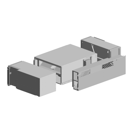
- Page 13 29. Lift the center service covers one at a time using appropriate lifting equipment. Attach the service cover slanted on to the middle rail; push the service cover up against the unit; and fasten it with the three screws provided. When lifting the service cover, a protective underlay must be placed beneath the cover to prevent scratches to the section.
- Page 14 The RC 1000 is intended to be installed in a non- industrial setting. Operation of the RC 1000 is intended to be done by layman through the AM 1000’s Airmaster Airlinq software. Maintenance, Repairs and De installation of the RC 1000 is only intended to be carried out by instructed personnel.
- Page 15 6. Fasten the RC 1000 module securely to the ceiling brackets using the provided screws. 7. Connect the brackets on the AM 1000 unit to the screws on the RC 1000 module. 8. Loosen the base plate containing the control box (AQC) and lower it.
-
Page 16: Ducts And Wall Grilles
Remember to seal around the penetrations. See section “3.6 Sealing the Gaps Around Ducts”. For the AM 1000 (Versions H, S1, S2) you have to use Ø400 wall grilles and reduction pieces Ø400 to Ø315 in the wall. Does not apply to Airmaster Boomerain® Wall 3.5. -
Page 17: Fitting Of Panels
Sealing on the inside between the ducts (3) and the Perforated section for exhaust for H version. wall/ceiling (2) can also be performed between the air Perforated section for supply for H version. handling unit (1) and the wall/roof (2) at position (5) before Perforated section for supply in S1 version or fitting the air handling unit. -
Page 18: Appendix 1 Dimension Drawings
Appendix 1 Dimension Drawings AM 1000 HH TT Appendix 1 - 18... -
Page 19: Am 1000 Hh Bb
AM 1000 HH BB Appendix 1 - 19... -
Page 20: Am 1000 Hh Dide
AM 1000 HH DIDE Appendix 1 - 20... -
Page 21: Am 1000 Hv Tb
AM 1000 HV TB Appendix 1 - 21... -
Page 22: Am 1000 Vv Tt
AM 1000 VV TT Appendix 1 - 22... -
Page 23: Am 1000 Vv Bb
AM 1000 VV BB Appendix 1 - 23... -
Page 24: Am 1000 Vv De
AM 1000 VV DE Appendix 1 - 24... -
Page 25: Am 1000 S1S2 Bb
AM 1000 S1S2 BB Appendix 1 - 25... - Page 26 AM-RC 1000 HHTT Appendix 1 - 26...
-
Page 27: Version Overview
Version overview Exhaust and supply position Exhaust Supply Horizontal S1S2 Vertical Side (towards the rear) Side (towards the front) HRE: Horizontal - Rectangular S1RE: Side-Rectangular (towards the rear) HRE HRE S1RE S2RE S2RE: Side-Rectangular (towards the front) Inlet and extract position Inlet Extract Bottom... -
Page 28: Holes To Be Drilled For Air Ducts (Hv, Vv))
Holes to be Drilled for Air Ducts (HV, VV)) < 60 mm > 1500 > 1500 + 30 + 30 > 60 mm > 1500 > 1500 1 = Exhaust 2 = Supply Appendix 1 - 28... - Page 29 - This page is intentionally left blank -...
- Page 30 - This page is intentionally left blank -...
- Page 31 - This page is intentionally left blank -...
- Page 32 Airmaster A/S Tel.: +45 98 62 48 22 Industrivej 59 info@airmaster-as.com DK-9600 Aars www.airmaster-as.com/en/...
Need help?
Do you have a question about the AM 1000 and is the answer not in the manual?
Questions and answers