
Related Manuals for Velleman DVM040


Summary of Contents for Velleman DVM040
- Page 1 DVM040 CATIII 1000V – CATIV 600V USER MANUAL HANDLEIDING MODE D'EMPLOI BEDIENUNGSANLEITUNG MANUAL DEL USUARIO INSTRUKCJA OBSŁUGI MANUAL DO UTILIZADOR...
- Page 2 DVM040 V. 01 – 04/05/2023 ©Velleman Group nv...
- Page 3 Respect the local environmental rules. If in doubt, contact your local waste disposal authorities. Thank you for choosing Velleman! Please read the manual thoroughly before bringing this device into service. If the device was damaged in transit, do not install or use it and contact your dealer.
-
Page 4: General Guidelines
DVM040 Continuity 3. General Guidelines Refer to the Velleman ® Service and Quality Warranty on the last pages of this manual. This symbol indicates: Read instructions Not reading the instructions and manual can lead to damage, injury or death. This symbol indicates: Danger A hazardous condition or action that may result in injury or death. -
Page 5: Maintenance
Do not touch unused terminals when the meter is linked to a circuit which is being tested. • Never use the meter with CAT III installations when measuring voltages that might exceed the safety margin of 1000 V above earth ground. V. 01 – 04/05/2023 ©Velleman Group nv... -
Page 6: General Description
DMMs are categorized depending on the risk and severity of transient overvoltage that might occur at the point of test. Transients are short-lived bursts of energy induced in a system, e.g. caused by lightning strike on a power line. V. 01 – 04/05/2023 ©Velleman Group nv... -
Page 7: Pollution Degree
DVM indicates in which environment the device may be used. Pollution No pollution or only dry, nonconductive pollution occurs. The degree 1 pollution has no influence. (only to be found in hermetically sealed enclosures) V. 01 – 04/05/2023 ©Velleman Group nv... -
Page 8: Specifications
CAT III 1000 V / CAT IV 600 V, L = 100 cm Display Counts 2000 Counts LCD Size (mm) 56 x 32 DC Voltage: 200mV / 2V / 20V / 200V / 1000V V. 01 – 04/05/2023 ©Velleman Group nv... - Page 9 Maximum input voltage: 1000V DC or 750V AC RMS Frequency range: 40Hz - 400Hz, Display: TRUE RMS Range Resolution DCV Accuracy ACV Accuracy 200mV 100µV ±0.5%±3 ±1.0%±5 ±0.8%±3 ±1.0%±5 10mV ±0.8%±3 ±1.0%±5 200V 100mV ±0.8%±3 ±1.0%±5 1000(750)V ±1%±5 ±1.2%±5 V. 01 – 04/05/2023 ©Velleman Group nv...
- Page 10 100Ω ±0.8%±5 2MΩ 1kΩ ±0.8%±5 20MΩ 10kΩ ±1.0%±10 200MΩ 0.1MΩ ±5%±10 Overload protection: 250 V DC or AC rms 9.4 DIODE AND CONTINUITY Do not conduct diode or continuity measurements on live circuits. V. 01 – 04/05/2023 ©Velleman Group nv...
- Page 11 Range Resolution Accuracy ±(4.0% reading + 25 digits) 10nF 0.01nF 100nF 0.1nF 1µF 0.001µF ±(4.0% reading + 15 digits) 10µF 0.01µF 100µF 0.1µF 1µF ±(5.0% reading + 25 digits) 10mF 10µF 100mF 100µF V. 01 – 04/05/2023 ©Velleman Group nv...
-
Page 12: Operation
• To avoid electrical shock and/or damage to the instrument, do not attempt to take any voltage measurement that might exceed 750VRMS. V. 01 – 04/05/2023 ©Velleman Group nv... -
Page 13: Dc Current Measurement
250V, do not place the test leads in parallel with a circuit or component when the test leads are plugged into the current terminals • An over-range is indicated by OL or -OL. Set to a higher range. V. 01 – 04/05/2023 ©Velleman Group nv... -
Page 14: Resistance Measurement
Touch the test probe tips to the circuit or wire you wish to check, the max. value of resistance under check will be showed in display, if the resistance is less than 100Ω, the audible signal will sound. V. 01 – 04/05/2023 ©Velleman Group nv... -
Page 15: Inductance Measurement
“°C/°F V Hz % mF” jack. Touch the test leads to the capacitor to be tested and read the capacitance value in the display. V. 01 – 04/05/2023 ©Velleman Group nv... -
Page 16: Frequency Measurement
Set the rotary switch to NCV position, connect the red test lead to “°C/°F V Hz % mF” jack. Contact the red test lead to live wire, the buzzer of meter will be activated and red LED will be flickered, V. 01 – 04/05/2023 ©Velleman Group nv... -
Page 17: Relative Mode
10 seconds. 10.13 HOLD FUNCTION The hold function freezes the reading in the display, press the HOLD button momentarily to activate or to exit the hold function. V. 01 – 04/05/2023 ©Velleman Group nv... -
Page 18: Battery And Fuse Replacement
Fuses: F 0.50 A / 1000 V, 6.35 x 32 mm & F 10A / 1000V, 6.35 x 32 mm Make sure the meter is closed tight and put the protective edge back in place before using the meter. V. 01 – 04/05/2023 ©Velleman Group nv... -
Page 19: Troubleshooting
© COPYRIGHT NOTICE The copyright to this manual is owned by Velleman Group nv. All worldwide rights reserved. No part of this manual may be copied, reproduced, translated or reduced to any electronic medium or otherwise without the prior written consent of the copyright holder. - Page 20 Neem in geval van twijfel contact op met de plaatselijke afvalverwerkingsautoriteiten. Bedankt dat u voor Velleman heeft gekozen! Lees de handleiding grondig door voordat u dit apparaat in gebruik neemt. Indien het toestel tijdens het transport beschadigd werd, installeer of gebruik het dan niet en neem contact op met uw dealer.
-
Page 21: Algemene Richtlijnen
DVM040 Condensator Diode Continuïteit 3. Algemene richtlijnen Zie de Velleman ® Service- en kwaliteitsgarantie op de laatste pagina's van deze handleiding. Dit symbool geeft aan: Lees instructies Het niet lezen van de instructies en handleiding kan leiden tot schade, letsel of de dood. -
Page 22: Tijdens Gebruik
Gebruik geen schuurmiddelen of oplosmiddelen op de meter. Gebruik voor het schoonmaken een vochtige doek en een mild schoonmaakmiddel. 5. Tijdens gebruik Gevaar voor elektrische schokken tijdens gebruik. Wees zeer voorzichtig bij het meten van circuits onder spanning. V. 01 – 04/05/2023 ©Velleman Group nv... -
Page 23: Algemene Beschrijving
Steek het rode meetsnoer in deze connector om een maximale stroom van 10 A te meten. "L/µA/mA" aansluiting Steek het rode meetsnoer in deze connector om een maximale stroom van 500 mA te meten. V. 01 – 04/05/2023 ©Velleman Group nv... - Page 24 I-, CAT II- en CAT III-omgevingen en op het niveau van de primaire voeding. Merk op dat voor alle metingen aan apparatuur waarvan de voedingskabels buiten lopen (bovengronds of ondergronds) een CAT IV-meter moet worden gebruikt. V. 01 – 04/05/2023 ©Velleman Group nv...
- Page 25 61010-1 vervuilingsgraad 2. Dit houdt in dat er bepaalde gebruiksbeperkingen gelden die verband houden met de vervuiling die in de gebruiksomgeving kan optreden. Zie bovenstaande tabel. Dit apparaat is alleen geschikt voor metingen in omgevingen van vervuilingsgraadklasse 2. V. 01 – 04/05/2023 ©Velleman Group nv...
- Page 26 Bereik selecteren Handmatig bereik Continuïteitscontrole Diode Test Data Hold Batterijtest (1,5V/3V/9V) Geen Indicatie over bereik LED/flitslicht Geen Achtergrondverlichting Automatische uitschakeling Weergave van eenheidspictogrammen Lage Batterij Indicatie Bescherming tegen overschrijding NCV Opsporing Detectie van stroomdraden V. 01 – 04/05/2023 ©Velleman Group nv...
- Page 27 10µA ±1.0%±5 ±1.5%±5 200mA 100µA ±1.0%±5 ±1.5%±5 ±1.5%±10 ±1.8%±15 10mA ±1.5%±10 ±1.8%±15 Bescherming tegen overbelasting: F 0,50 A / 1000 V, 6,35 x 32 mm F 10A / 1000V, 6,35 x 32 mm V. 01 – 04/05/2023 ©Velleman Group nv...
- Page 28 Het display geeft bij benadering de doorlaatspanning van de diode aan. ingebouwde zoemer klinkt als weerstand < 100 Ω 9.5 TEMPERATUUR Eenh Nauwkeurigheid Bereik Resolutie -20℃~ 0℃ ±4℃ ±(2.0%+3d) 0℃~400℃ ℃ 1℃ ±(3.0%+3d) 400℃~1000℃ -4℉~50℉ ±5℉ ℉ 1℉ ±(2.0%+5d) 50℉~750℉ V. 01 – 04/05/2023 ©Velleman Group nv...
- Page 29 9.8 FREQUENTIE Bereik Resolutie Nauwkeurigheid 10Hz 0.01Hz 100Hz 0.1Hz 1kHz 0,001kHz 10kHz 0.01kHz ±(0,1% aflezing + 2 cijfers) 100kHz 0.1kHz 1MHz 0.001MHz 10MHz 0.01MHz V. 01 – 04/05/2023 ©Velleman Group nv...
-
Page 30: Dc-Stroommeting
Meet geen circuits die spanningen > 1000 VDC of > 750 VAC kunnen bevatten. Wees uiterst voorzichtig bij het meten van spanningen hoger dan 60 VDC of 30 VAC rms. Plaats uw vingers tijdens het meten altijd achter de beschermranden van de testsondes! V. 01 – 04/05/2023 ©Velleman Group nv... - Page 31 Raak met de punten van de testsonde het te testen circuit of onderdeel aan. Het beste is om één kant van het te testen onderdeel los te koppelen, zodat de rest van het circuit de weerstandsmeting niet verstoort. Lees de weerstand af op het LCD-scherm V. 01 – 04/05/2023 ©Velleman Group nv...
- Page 32 • Meet, om elektrische schokken te voorkomen, nooit de continuïteit op circuits van draden met spanning. V. 01 – 04/05/2023 ©Velleman Group nv...
- Page 33 10.7 FREQUENTIEMETING Om elektrische schokken te voorkomen, mag u niet meer dan 250 V DC of 250 V AC rms toepassen voordat u de frequentie meet. V. 01 – 04/05/2023 ©Velleman Group nv...
- Page 34 LED niet flikkeren. Opmerkingen • Wanneer de kring in ernstige lekkage is (ongeveer over 15V), zal de rode testkabel zelfs de aardingslijn contacteren, de zoemer van meter zal klinken en LED zal flikkeren. V. 01 – 04/05/2023 ©Velleman Group nv...
- Page 35 10 seconden. 10.13 VASTE FUNCTIE De hold-functie bevriest de meting op het display, druk kort op de HOLD- toets om de hold-functie te activeren of te verlaten. V. 01 – 04/05/2023 ©Velleman Group nv...
- Page 36 Verwijder de defecte zekering en plaats een nieuwe. • Sluit de behuizing en draai de schroef vast. Zekeringen: F 0,50 A / 1000 V, 6,35 x 32 mm & F 10A / 1000V, 6,35 x 32 V. 01 – 04/05/2023 ©Velleman Group nv...
-
Page 37: Problemen Oplossen
(verkeerd) gebruik van dit toestel. Voor meer info over dit product en de laatste versie van deze handleiding kunt u terecht op onze website www.velleman.eu. De informatie in deze handleiding kan zonder voorafgaande kennisgeving worden gewijzigd. - Page 38 En cas de doute, contactez les autorités locales chargées de l'élimination des déchets. Merci d'avoir choisi Velleman ! Veuillez lire attentivement le manuel avant de mettre cet appareil en service. Si l'appareil a été endommagé pendant le transport, ne l'installez pas, ne l'utilisez pas et contactez votre revendeur.
- Page 39 DVM040 Continuité 3. Lignes directrices générales Reportez-vous à la garantie de service et de qualité Velleman ® qui figure dans les dernières pages de ce manuel. Ce symbole indique : Lire les instructions Ne pas lire les instructions et le manuel peut entraîner des dommages, des blessures ou la mort.
-
Page 40: Pendant L'utilisation
N'appliquez pas de produits abrasifs ou de solvants sur le lecteur. Utilisez un chiffon humide et un détergent doux pour le nettoyage. 5. Pendant l'utilisation Risque de choc électrique pendant le fonctionnement. Soyez très prudent lorsque vous mesurez des circuits sous tension. V. 01 – 04/05/2023 ©Velleman Group nv... -
Page 41: Description Générale
Insérez le fil de test rouge dans ce connecteur afin de mesurer un courant maximum de 10 A. "Prise "L/µA/mA Insérez le fil de test rouge dans ce connecteur afin de mesurer un courant maximum de 500 mA. V. 01 – 04/05/2023 ©Velleman Group nv... - Page 42 CAT III 1000 V. Cela implique que certaines restrictions d'utilisation s'appliquent en ce qui concerne les tensions et les pics de tension qui peuvent se produire dans l'environnement d'utilisation. Voir le tableau ci-dessus. V. 01 – 04/05/2023 ©Velleman Group nv...
-
Page 43: Degré De Pollution
Reportez-vous au tableau ci-dessus. Cet appareil ne convient que pour des mesures dans des environnements de degré de pollution de classe 2. V. 01 – 04/05/2023 ©Velleman Group nv... -
Page 44: Spécifications
Maintien des données Test de batterie (1,5V/3V/9V) Indication de dépassement de gamme Lumière LED/flash Rétro-éclairage Arrêt automatique Affichage de l'icône de l'unité Indication de pile faible Protection contre le dépassement Détection de NCV V. 01 – 04/05/2023 ©Velleman Group nv... - Page 45 ±1.5%±5 200mA 100µA ±1.0%±5 ±1.5%±5 ±1.5%±10 ±1.8%±15 10mA ±1.5%±10 ±1.8%±15 Protection contre les surcharges : F 0,50 A / 1000 V, 6,35 x 32 mm F 10A / 1000V, 6.35 x 32 mm V. 01 – 04/05/2023 ©Velleman Group nv...
- Page 46 L'avertisseur sonore intégré retentit si la résistance est < 100 Ω 9.5 TEMPERATURE Précision Unité Gamme Résolution -20℃~ 0℃ ±4℃ ±(2.0%+3d) 0℃~400℃ ℃ 1℃ ±(3.0%+3d) 400℃~1000℃ -4℉~50℉ ±5℉ ℉ 1℉ ±(2.0%+5d) 50℉~750℉ V. 01 – 04/05/2023 ©Velleman Group nv...
- Page 47 Résolution Précision 10Hz 0,01Hz 100Hz 0,1Hz 1kHz 0,001kHz 10kHz 0,01kHz ±(0,1% lecture + 2 chiffres) 100kHz 0,1kHz 1MHz 0,001 MHz 10MHz 0,01MHz Protection contre les surcharges : 250 V DC ou AC rms V. 01 – 04/05/2023 ©Velleman Group nv...
- Page 48 Soyez extrêmement prudent lorsque vous mesurez des tensions supérieures à 60 VDC ou 30 VAC rms. Lors des mesures, placez toujours vos doigts derrière les bords de protection des sondes de test ! V. 01 – 04/05/2023 ©Velleman Group nv...
-
Page 49: Mesure De La Résistance
Touchez les pointes des sondes de test sur le circuit ou la pièce testée. Il est préférable de déconnecter un côté de la pièce testée afin que le reste du circuit n'interfère pas avec la lecture de la résistance. Lire la résistance sur l'écran LCD V. 01 – 04/05/2023 ©Velleman Group nv... -
Page 50: Test De Diode Et De Continuité
être variable en fonction de la résistance d'autres voies entre les pointes de la sonde. • Pour éviter les chocs électriques, ne mesurez jamais la continuité sur des circuits de fils sous tension. V. 01 – 04/05/2023 ©Velleman Group nv... -
Page 51: Mesure De L'inductance
10.7 MESURE DE LA FRÉQUENCE Pour éviter tout choc électrique, ne pas appliquer plus de 250V DC ou 250V AC rms avant d'effectuer une mesure de fréquence. V. 01 – 04/05/2023 ©Velleman Group nv... - Page 52 à un fil sous tension, le buzzer de l'appareil se déclenche et la LED rouge clignote. Lorsque le fil d'essai rouge est connecté à la ligne de terre, le buzzer ne se déclenche pas et la LED ne clignote pas. Notes V. 01 – 04/05/2023 ©Velleman Group nv...
-
Page 53: Fonction Hold
Le rétroéclairage s'éteint automatiquement au bout de 10 secondes. 10.13 FONCTION HOLD La fonction de maintien fige la lecture sur l'écran. Appuyez brièvement sur la touche HOLD pour activer ou quitter la fonction de maintien. V. 01 – 04/05/2023 ©Velleman Group nv... - Page 54 Retirer le fusible défectueux et en insérer un nouveau. • Fermez le boîtier et fixez la vis. Fusibles : F 0,50 A / 1000 V, 6,35 x 32 mm & F 10A / 1000V, 6,35 x 32 V. 01 – 04/05/2023 ©Velleman Group nv...
-
Page 55: Dépannage
être modifiées sans préavis. © AVIS DE DROIT D'AUTEUR Le copyright de ce manuel est la propriété de Velleman Group nv. Tous les droits mondiaux sont réservés. Aucune partie de ce manuel ne peut être copiée, reproduite, traduite ou réduite sur un support électronique ou autre sans l'accord écrit préalable du détenteur des droits d'auteur. - Page 56 Wenden Sie sich im Zweifelsfall an Ihre örtliche Abfallentsorgungsbehörde. Danke, dass Sie sich für Velleman entschieden haben! Bitte lesen Sie das Handbuch sorgfältig durch, bevor Sie das Gerät in Betrieb nehmen. Sollte das Gerät beim Transport beschädigt worden sein, installieren oder benutzen Sie es nicht und wenden Sie sich an Ihren Händler.
- Page 57 DVM040 Kondensator Diode Kontinuität 3. Allgemeine Leitlinien Siehe die Velleman ® Service- und Qualitätsgarantie auf den letzten Seiten dieses Handbuchs. Dieses Symbol zeigt an: Anweisungen lesen Das Nichtlesen der Anweisungen und des Handbuchs kann zu Schäden, Verletzungen oder Tod führen.
-
Page 58: Wartung
Anweisungen zum Auswechseln der Batterie oder der Sicherung finden Sie in §11 Batterie- und Sicherungswechsel. Verwenden Sie keine Scheuermittel oder Lösungsmittel für das Messgerät. Verwenden Sie zur Reinigung ein feuchtes Tuch und ein mildes Reinigungsmittel. V. 01 – 04/05/2023 ©Velleman Group nv... -
Page 59: Während Der Benutzung
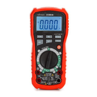
Siehe dazu die Abbildung auf Seite 2 dieser Anleitung: Berührungslose Spannung (NCV) Induktionsstellung LED-Anzeige Beleuchtetes LCD-Display Funktionstasten Drehbarer Schalter Buchse "10A" Stecken Sie die rote Messleitung in diese Buchse, um einen Maximalstrom von 10 A zu messen. V. 01 – 04/05/2023 ©Velleman Group nv... - Page 60 II- und CAT III-Umgebungen sowie auf der Primärversorgungsebene geeignet. Beachten Sie, dass für alle Messungen an Geräten, bei denen die Versorgungskabel im Freien verlaufen (entweder freiliegend oder unterirdisch), ein CAT IV-Messgerät verwendet werden muss. V. 01 – 04/05/2023 ©Velleman Group nv...
- Page 61 Die Verschmutzung erzeugt eine anhaltende Leitfähigkeit, die durch leitfähigen Staub, Regen oder Schnee verursacht wird (exponierte Umgebungen im Freien und Umgebungen, in denen eine hohe Luftfeuchtigkeit oder eine hohe Konzentration von Feinstaub auftritt). V. 01 – 04/05/2023 ©Velleman Group nv...
-
Page 62: Spezifikationen
200μA / 2mA / 20mA / 200mA /2A / 10A 200Ω / 2kΩ / 20kΩ / 200kΩ / 2MΩ / 20MΩ Widerstandsfähigkeit: /200M Ω Bereich wählen Manueller Bereich Kontinuitätsprüfung Diodentest Daten halten Batterietest (1,5V/3V/9V) Nein Anzeige der Bereichsüberschreitung V. 01 – 04/05/2023 ©Velleman Group nv... -
Page 63: Gleich- Und Wechselspannung
±1.0%±5 1000(750)V ±1%±5 ±1.2%±5 9.2 GLEICH- UND WECHSELSTROM Überlastschutz: Sicherung F500mA/1000V für mA- Bereich Sicherung F10A/1000V für 10A-Bereich Frequenzbereich: 40Hz - 400Hz, Anzeige: TRUE RMS Bereich Auflösung DCA-Genauigkeit ACA-Genauigkeit 200uA 0,1µA ±1.0%±5 ±1.5%±5 V. 01 – 04/05/2023 ©Velleman Group nv... - Page 64 Überlastungsschutz: 250 V DC oder AC rms 9.4 DIODE UND DURCHGANG Führen Sie keine Dioden- oder Durchgangsmessungen an spannungsführenden Stromkreisen durch. Bereich Beschreibung Die Anzeige zeigt die ungefähre Durchlassspannung der Diode eingebauter Summer ertönt bei Widerstand < 100 Ω V. 01 – 04/05/2023 ©Velleman Group nv...
- Page 65 Überlastschutz: 250V DC oder 250V AC RMS Hinweis: Es ist normal, wenn der kleine Kapazitätswert nicht auf Null zurückgeht, ziehen Sie die Messwerte während der Messung ab, um den genauen Wert zu erhalten. V. 01 – 04/05/2023 ©Velleman Group nv...
- Page 66 Geräts zu vermeiden, sollten Sie keine Spannungsmessungen vornehmen, die 750VRMS überschreiten. • Dies ist eine normale Situation und hat keinen Einfluss auf die Messung. Sobald Sie sich im mV- oder V-Bereich befinden, zeigt V. 01 – 04/05/2023 ©Velleman Group nv...
- Page 67 Potenzial von mehr als 250 V zu erden. Legen Sie die Messleitungen nicht parallel zu einem Stromkreis oder einer Komponente, wenn die Messleitungen in die Stromklemmen eingesteckt sind. • Eine Bereichsüberschreitung wird durch OL oder -OL angezeigt. Auf einen höheren Bereich einstellen. V. 01 – 04/05/2023 ©Velleman Group nv...
- Page 68 COM-Buchse, den roten Bananenstecker der Messleitung in die positive "°C/°F V Hz % mF" Buchse. Legen Sie die rote Messleitung an die Anode der Diode und die schwarze Messleitung an die Kathode der Diode, das Messgerät zeigt V. 01 – 04/05/2023 ©Velleman Group nv...
- Page 69 Messwerte beruhigt haben, bevor Sie den Test beenden. 10.6 KAPAZITÄTSMESSUNG Führen Sie keine Kapazitätsmessungen an stromführenden Stromkreisen durch. Stellen Sie sicher, dass alle Kondensatoren im Stromkreis entladen sind. Stellen Sie den Drehschalter auf den gewünschten Kapazitätsbereich (C). V. 01 – 04/05/2023 ©Velleman Group nv...
- Page 70 Messgeräts mit dem zu prüfenden Stromkreis, die Anzeige-LED blinkt und ein akustisches Signal ertönt, die Signalstärke wird im LCD- Display angezeigt. Anmerkungen • Das Erkennungsergebnis dient nur als Referenz, bestimmen Sie die Spannung nicht ausschließlich durch die NCV-Erkennung. V. 01 – 04/05/2023 ©Velleman Group nv...
- Page 71 Drücken Sie die REL-Taste, um den Messwert in der LCD-Anzeige zu speichern, und die REL-Anzeige erscheint in der LCD-Anzeige. Auf dem LCD-Display wird die Differenz zwischen dem gespeicherten Wert und dem gemessenen Wert angezeigt V. 01 – 04/05/2023 ©Velleman Group nv...
-
Page 72: Display-Hintergrundbeleuchtung
Entfernen Sie die alte Batterie und setzen Sie eine neue ein. • Schließen Sie das Gehäuse und ziehen Sie die Schraube fest. Batterie: 9V (6F22) x 1, bitte achten Sie auf die Polarität V. 01 – 04/05/2023 ©Velleman Group nv... -
Page 73: Fehlersuche
Die Informationen in diesem Handbuch können ohne vorherige Ankündigung geändert werden. © COPYRIGHT-VERMERK Das Urheberrecht an diesem Handbuch liegt bei der Velleman Group nv. Alle weltweiten Rechte vorbehalten. Kein Teil dieses Handbuchs darf ohne die vorherige schriftliche Zustimmung des Urheberrechtsinhabers kopiert, reproduziert, übersetzt oder auf ein elektronisches Medium oder... -
Page 74: Manual Del Usuario
En caso de duda, póngase en contacto con las autoridades locales de eliminación de residuos. Gracias por elegir Velleman. Lea detenidamente el manual antes de poner en servicio este aparato. Si el aparato ha resultado dañado durante el transporte, no lo instale ni lo utilice y póngase en contacto con su distribuidor. -
Page 75: Directrices Generales
DVM040 Condensador Diodo Continuidad 3. Directrices generales Consulte la garantía de servicio y calidad de Velleman ® en las últimas páginas de este manual. Este símbolo indica: Leer instrucciones No leer las instrucciones y el manual puede provocar daños, lesiones o la muerte. -
Page 76: Mantenimiento
Riesgo de descarga eléctrica durante el funcionamiento. Tenga mucho cuidado al medir circuitos bajo tensión. • Si el equipo se utiliza de una manera no especificada por el fabricante, la protección proporcionada por el equipo puede verse afectada. V. 01 – 04/05/2023 ©Velleman Group nv... -
Page 77: Descripción General
Inserte el cable de prueba rojo en este conector para medir una corriente máxima de 500 mA. "Conector "°C/°F V Hz % C Inserte el cable de prueba rojo (positivo) en este conector para medir la tensión y la resistencia. V. 01 – 04/05/2023 ©Velleman Group nv... -
Page 78: Categoría De Sobretensión/Instalación
Consulte la tabla anterior. Este dispositivo sólo es adecuado para mediciones de hasta 1000 V en CAT III o hasta 600 V en CAT IV. V. 01 – 04/05/2023 ©Velleman Group nv... -
Page 79: Especificaciones
Este aparato no está calibrado en el momento de la compra. Normativa relativa al entorno de uso: Utilice este medidor sólo para mediciones en entornos CAT I, CAT II, CAT III y CAT IV (véase §7). V. 01 – 04/05/2023 ©Velleman Group nv... - Page 80 Protección contra el exceso de Sí alcance Detección NCV Sí Detección de cables con Sí corriente Medición RMS real Sí Batería 9V (6F22) x 1 Tamaño del producto (mm) 200x92x60 Peso del producto (g) V. 01 – 04/05/2023 ©Velleman Group nv...
- Page 81 200 mA 100µA ±1.0%±5 ±1.5%±5 1 mA ±1.5%±10 ±1.8%±15 10 mA ±1.5%±10 ±1.8%±15 Protección contra sobrecarga: F 0,50 A / 1000 V, 6,35 x 32 mm F 10A / 1000V, 6,35 x 32 mm V. 01 – 04/05/2023 ©Velleman Group nv...
- Page 82 < 100 Ω 9.5 TEMPERATURA Unid Precisión Gama Resolución -20℃~ 0℃ ±4℃ ±(2.0%+3d) 0℃~400℃ ℃ 1℃ ±(3.0%+3d) 400℃~1000℃ -4℉~50℉ ±5℉ ℉ 1℉ ±(2.0%+5d) 50℉~750℉ V. 01 – 04/05/2023 ©Velleman Group nv...
- Page 83 Resolución Precisión 10 Hz 0,01 Hz 100 Hz 0,1 Hz 1kHz 0,001 kHz 10 kHz 0,01 kHz ±(0,1% lectura + 2 dígitos) 100 kHz 0,1 kHz 1MHz 0,001 MHz 10 MHz 0,01 MHz V. 01 – 04/05/2023 ©Velleman Group nv...
-
Page 84: Operación
Extreme las precauciones al medir tensiones superiores a 60 V CC o 30 V CA rms. Durante la medición, coloque siempre los dedos detrás de los bordes protectores de las puntas de prueba. V. 01 – 04/05/2023 ©Velleman Group nv... -
Page 85: Medición De La Resistencia
Toque con las puntas de las sondas el circuito o la pieza a comprobar. Lo mejor es desconectar un lado de la pieza bajo prueba para que el resto del circuito no interfiera con la lectura de la resistencia. Leer la resistencia en la pantalla LCD V. 01 – 04/05/2023 ©Velleman Group nv... -
Page 86: Prueba De Diodo Y Continuidad
• Para evitar descargas eléctricas, nunca mida la continuidad en circuitos de cables que con tensión. V. 01 – 04/05/2023 ©Velleman Group nv... -
Page 87: Medición De Inductancia
COM, inserte el conector banana del cable de prueba rojo en la toma positiva "°C/°F V Hz % mF". Toque con los cables de prueba el condensador que desea comprobar y lea el valor de la capacitancia en la pantalla. V. 01 – 04/05/2023 ©Velleman Group nv... -
Page 88: Medición De Frecuencia
NCV y la pantalla LCD EF, contacte la parte superior del medidor con el circuito bajo prueba, el LED indicador parpadeará y sonará una señal audible, la intensidad de la señal se muestra en la pantalla LCD. Notas V. 01 – 04/05/2023 ©Velleman Group nv... - Page 89 Pulse el botón REL para almacenar la lectura en la pantalla LCD y el indicador REL aparecerá en la pantalla LCD. La pantalla LCD indicará la diferencia entre el valor memorizado y el valor medido V. 01 – 04/05/2023 ©Velleman Group nv...
-
Page 90: Función Hold
Pila: 9V (6F22) x 1, asegúrese de respetar la polaridad • Antes de sustituir el fusible, asegúrese de que el multímetro está desconectado de la fuente de tensión externa y de otros instrumentos conectados. V. 01 – 04/05/2023 ©Velleman Group nv... -
Page 91: Solución De Problemas
© AVISO DE COPYRIGHT El copyright de este manual es propiedad de Velleman Group nv. Reservados todos los derechos en todo el mundo. Ninguna parte de este manual puede ser copiada, reproducida, traducida o reducida a ningún medio electrónico o de otro tipo sin el consentimiento previo por escrito del... -
Page 92: Instrukcja Obsługi
W razie wątpliwości należy skontaktować się z lokalnymi władzami zajmującymi się utylizacją odpadów. Dziękujemy za wybór firmy Velleman! Prosimy o dokładne zapoznanie się z instrukcją obsługi przed wprowadzeniem urządzenia do użytku. Jeśli urządzenie zostało uszkodzone w transporcie, nie należy go instalować ani używać... - Page 93 Pozwoli to uniknąć kondensacji i błędów pomiarowych. Chroń to urządzenie przed wstrząsami i nadużyciami. Unikaj brutalnej siły podczas obsługi. Stopień zanieczyszczenia 2 urządzenia. Tylko do użytku wewnątrz pomieszczeń. Urządzenie należy trzymać z dala od deszczu, V. 01 – 04/05/2023 ©Velleman Group nv...
- Page 94 Instrukcje dotyczące wymiany baterii lub bezpiecznika znajdują się w §11 Wymiana baterii i bezpiecznika. Nie należy stosować materiałów ściernych ani rozpuszczalników do miernika. Do czyszczenia należy używać wilgotnej szmatki i łagodnego detergentu. V. 01 – 04/05/2023 ©Velleman Group nv...
-
Page 95: Opis Ogólny
Patrz ilustracja na stronie 2 niniejszej instrukcji: Bezkontaktowe napięcie (NCV) pozycja indukcyjna Wskaźnik LED Podświetlany wyświetlacz LCD Przyciski funkcyjne Przełącznik obrotowy Gniazdo "10A" Włóż czerwony przewód pomiarowy do tego złącza, aby zmierzyć maksymalny prąd 10 A. V. 01 – 04/05/2023 ©Velleman Group nv... - Page 96 Miernik o klasie CAT IV nadaje się do pomiarów w środowisku CAT I, CAT II i CAT III oraz na poziomie zasilania podstawowego. Należy pamiętać, że do wszystkich pomiarów urządzeń, dla których kable zasilające biegną na zewnątrz (napowietrzne lub podziemne) należy stosować miernik CAT IV. V. 01 – 04/05/2023 ©Velleman Group nv...
-
Page 97: Stopień Zanieczyszczenia
Stopień Zanieczyszczenie powoduje trwałe przewodnictwo zanieczyszczenia spowodowane przez przewodzący pył lub przez deszcz lub śnieg (narażone środowiska zewnętrzne i środowiska, w których występuje wysoki poziom wilgotności lub wysokie stężenie drobnych cząstek) V. 01 – 04/05/2023 ©Velleman Group nv... - Page 98 200μA / 2mA / 20mA / 200mA /2A / 10A 200Ω / 2kΩ / 20kΩ / 200kΩ / 2MΩ / 20MΩ Odporność: /200M Ω Wybór zakresu Zakres ręczny Kontrola ciągłości Test diody Data Hold Test baterii (1,5V/3V/9V) Wskazanie przekroczenia zakresu V. 01 – 04/05/2023 ©Velleman Group nv...
- Page 99 ±1.0%±5 200V 100mV ±0.8%±3 ±1.0%±5 1000(750)V ±1%±5 ±1.2%±5 9.2 PRĄD STAŁY I PRZEMIENNY Zabezpieczenie przed przeciążeniem: bezpiecznik F500mA/1000V dla zakresu mA bezpiecznik F10A/1000V dla zakresu 10A Zakres częstotliwości: 40Hz - 400Hz, Wyświetlacz: TRUE V. 01 – 04/05/2023 ©Velleman Group nv...
- Page 100 Zabezpieczenie przed przeciążeniem: 250 V DC lub AC rms 9.4 DIODA I CIĄGŁOŚĆ Nie należy przeprowadzać pomiarów diody lub ciągłości na obwodach pod napięciem. zakres opis na wyświetlaczu odczytuje się przybliżone napięcie zasilania diody V. 01 – 04/05/2023 ©Velleman Group nv...
- Page 101 ±(5,0% odczytu + 25 cyfr) 10mF 10µF 100mF 100µF Zabezpieczenie przed przeciążeniem: 250V DC lub 250V AC RMS Uwaga: Jest to normalne, gdy mała wartość pojemności nie zwraca zera, odliczaj odczyty podczas pomiaru, aby uzyskać dokładną wartość. V. 01 – 04/05/2023 ©Velleman Group nv...
- Page 102 750VRMS. • Jest to normalna sytuacja i nie ma wpływu na pomiar, po wejściu w zakres mV lub V, nawet bez wejścia lub podłączenia przewodu pomiarowego, miernik pokazuje wartość na LCD. V. 01 – 04/05/2023 ©Velleman Group nv...
-
Page 103: Pomiar Prądu Stałego
250V, nie umieszczaj przewodów pomiarowych równolegle z obwodem lub komponentem, gdy przewody pomiarowe są podłączone do zacisków prądowych • Przekroczenie zakresu jest sygnalizowane przez OL lub -OL. Ustawić na wyższy zakres. V. 01 – 04/05/2023 ©Velleman Group nv... - Page 104 OL. Dotknij końcówki sondy do obwodu lub przewodu, który chcesz sprawdzić, maksymalna wartość sprawdzanej rezystancji zostanie pokazana na wyświetlaczu, jeśli rezystancja jest mniejsza niż 100Ω, usłyszysz sygnał dźwiękowy. V. 01 – 04/05/2023 ©Velleman Group nv...
-
Page 105: Pomiar Pojemności
Czarny wtyk bananowy przewodu pomiarowego włożyć do ujemnego gniazda COM, czerwony wtyk bananowy przewodu pomiarowego włożyć do dodatniego gniazda "°C/°F V Hz % mF". Dotknij przewodów pomiarowych do badanego kondensatora i odczytaj wartość pojemności na wyświetlaczu. V. 01 – 04/05/2023 ©Velleman Group nv... -
Page 106: Pomiar Częstotliwości
Wynik detekcji ma charakter referencyjny, nie należy określać napięcia TYLKO poprzez detekcję NCV. • Wykrywanie może być zakłócone przez konstrukcję gniazda, grubość izolacji i inne zmienne warunki. • Zewnętrzne źródła zakłóceń, takie jak latarka, silnik itp. mogą powodować błędne wykrywanie. V. 01 – 04/05/2023 ©Velleman Group nv... - Page 107 Naciśnij przycisk REL, aby zapisać odczyt na wyświetlaczu LCD, a na wyświetlaczu LCD pojawi się wskaźnik REL. Wyświetlacz LCD wskaże różnicę pomiędzy zapisaną wartością a wartością zmierzoną Naciśnij przycisk REL, aby wyjść z trybu względnego. V. 01 – 04/05/2023 ©Velleman Group nv...
-
Page 108: Podświetlenie Wyświetlacza
Przed wymianą bezpiecznika należy upewnić się, że multimetr jest odłączony od zewnętrznego źródła napięcia i innych podłączonych przyrządów. • Stosować wyłącznie bezpieczniki opisane w części dotyczącej danych technicznych! Stosowanie bezpieczników pomocniczych, w szczególności zwarcie oprawek bezpiecznikowych jest V. 01 – 04/05/2023 ©Velleman Group nv... -
Page 109: Rozwiązywanie Problemów
© NOTA O PRAWACH AUTORSKICH Prawa autorskie do niniejszej instrukcji są własnością firmy Velleman Group nv. Wszelkie prawa na całym świecie zastrzeżone. Żadna część niniejszej instrukcji nie może być kopiowana, reprodukowana, tłumaczona lub redukowana na jakimkolwiek nośniku elektronicznym lub w inny sposób bez uprzedniej pisemnej zgody właściciela praw autorskich. -
Page 110: Manual Do Utilizador
Em caso de dúvida, contactar as autoridades locais responsáveis pela eliminação de resíduos. Obrigado por ter escolhido a Velleman! Leia atentamente o manual antes de colocar este aparelho em funcionamento. Se o aparelho tiver sido danificado durante o transporte, não o instale nem utilize e contacte o seu revendedor. - Page 111 DVM040 Díodo Continuidade 3. Orientações gerais Consulte a Garantia de Qualidade e Assistência Técnica Velleman ® últimas páginas deste manual. Este símbolo indica: Ler instruções A não leitura das instruções e do manual pode provocar danos, ferimentos ou morte. Este símbolo indica: Perigo Uma condição ou acção perigosa que pode resultar em...
-
Page 112: Durante A Utilização
Risco de choque eléctrico durante o funcionamento. Tenha muito cuidado ao medir circuitos eléctricos. • Se o equipamento for utilizado de uma forma não especificada pelo fabricante, a protecção fornecida pelo equipamento pode ser prejudicada. V. 01 – 04/05/2023 ©Velleman Group nv... -
Page 113: Descrição Geral
500 mA. "Tomada "°C/°F V Hz % C Introduza o cabo de teste vermelho (positivo) neste conector para medir a tensão e a resistência. Tomada "COM" Introduzir o fio de teste preto (negativo). V. 01 – 04/05/2023 ©Velleman Group nv... - Page 114 Consulte a tabela acima. Este dispositivo só é adequado para medições até 1000 V em CAT III ou até 600 V em CAT IV V. 01 – 04/05/2023 ©Velleman Group nv...
- Page 115 Consulte a tabela acima. Este dispositivo só é adequado para medições em ambientes da classe 2 de grau de poluição. V. 01 – 04/05/2023 ©Velleman Group nv...
- Page 116 Indicação de excesso de gama Luz LED/flash Não Luz de fundo Desligamento automático Ecrã do ícone da unidade Indicação de bateria fraca Protecção contra excesso de alcance Detecção de NCV Detecção de fio vivo V. 01 – 04/05/2023 ©Velleman Group nv...
- Page 117 10µA ±1.0%±5 ±1.5%±5 200mA 100µA ±1.0%±5 ±1.5%±5 ±1.5%±10 ±1.8%±15 10mA ±1.5%±10 ±1.8%±15 Protecção contra sobrecarga: F 0,50 A / 1000 V, 6,35 x 32 mm F 10A / 1000V, 6,35 x 32 mm V. 01 – 04/05/2023 ©Velleman Group nv...
- Page 118 O sinal sonoro incorporado soa se a resistência for inferior a 100 Ω 9.5 TEMPERATURA Unid Exactidão Gama Resolução -20℃~ 0℃ ±4℃ ±(2.0%+3d) 0℃~400℃ ℃ 1℃ ±(3.0%+3d) 400℃~1000℃ -4℉~50℉ ±5℉ ℉ 1℉ ±(2.0%+5d) 50℉~750℉ V. 01 – 04/05/2023 ©Velleman Group nv...
- Page 119 9.8 FREQUÊNCIA Gama Resolução Exactidão 10Hz 0,01Hz 100Hz 0,1Hz 1kHz 0,001kHz 10kHz 0,01kHz ±(0,1% leitura + 2 dígitos) 100kHz 0,1 kHz 1MHz 0,001MHz 10MHz 0,01MHz Protecção contra sobrecarga: 250 V DC ou AC rms V. 01 – 04/05/2023 ©Velleman Group nv...
- Page 120 750 VAC Tenha muito cuidado ao medir tensões superiores a 60 VDC ou 30 VAC rms. Durante a medição, colocar sempre os dedos por trás dos bordos de protecção das sondas de teste! V. 01 – 04/05/2023 ©Velleman Group nv...
- Page 121 Encostar as pontas das sondas de teste ao circuito ou à peça em teste. É preferível desligar um lado da peça a testar para que o resto do circuito não interfira com a leitura da resistência. Ler a resistência no ecrã LCD V. 01 – 04/05/2023 ©Velleman Group nv...
- Page 122 10.5 MEDIÇÃO DA INDUTÂNCIA Coloque o interruptor rotativo na gama de indutância (L) pretendida. Comece com a definição H. Se o valor for inferior a 1 H, mude para a definição mH. V. 01 – 04/05/2023 ©Velleman Group nv...
- Page 123 10.7 MEDIÇÃO DE FREQUÊNCIA Para evitar choques eléctricos, não aplique mais de 250 V CC ou 250 V CA rms antes de efectuar medições de frequência. Coloque o selector rotativo na gama de frequências (Hz) pretendida. V. 01 – 04/05/2023 ©Velleman Group nv...
- Page 124 LED vermelho ficará intermitente; se o cabo de teste vermelho for ligado à linha de terra, o sinal sonoro não soará e o LED não ficará intermitente. Notas V. 01 – 04/05/2023 ©Velleman Group nv...
- Page 125 10 segundos. 10.13 FUNÇÃO HOLD A função de retenção congela a leitura no visor, pressione o botão HOLD momentaneamente para activar ou para sair da função de retenção. V. 01 – 04/05/2023 ©Velleman Group nv...
- Page 126 Fusíveis: F 0,50 A / 1000 V, 6,35 x 32 mm e F 10A / 1000V, 6,35 x 32 mm Certifique-se de que o aparelho está bem fechado e volte a colocar o rebordo de protecção no lugar antes de o utilizar. V. 01 – 04/05/2023 ©Velleman Group nv...
-
Page 127: Resolução De Problemas
© AVISO DE DIREITOS DE AUTOR Os direitos de autor deste manual são propriedade do Velleman Group nv. Todos os direitos mundiais reservados. Nenhuma parte deste manual pode ser copiada, reproduzida, traduzida ou reduzida para qualquer meio electrónico ou outro sem o consentimento prévio por escrito... - Page 128 • Indien de klacht gegrond is en een gratis reparatie of • Velleman® can decide to replace an article with an equivalent vervanging van een artikel onmogelijk is of indien de kosten article, or to refund the retail value totally or partially when the hiervoor buiten verhouding zijn, kan Velleman®...
- Page 129 Velleman®; • tuyau : il est conseillé de consulter la notice et de contrôler - se calcula gastos de transporte de y a Velleman® si el câbles, piles, etc. avant de retourner l’appareil. Un appareil aparato ya no está cubierto por la garantía.
- Page 130 6 (sześć) Erlaubnis von Velleman® vorgenommen werden. miesięcy; • Im Fall einer Reparatur, wenden Sie sich an Ihren Velleman®- - Szkody wynikające ze źle zabezpieczonej wysyłki produktu; Verteiler. Legen Sie das Produkt ordnungsgemäß verpackt - Wszelkie szkody spowodowane przez nieautoryzowaną...
- Page 131 Wraz z niesprawnym sem a autorização de SA Velleman®; produktem należy dołączyć jasny i szczegółowy opis jego - despesas de transporte de e para Velleman® se o aparelho usterki, wady; não estiver coberto pela garantia. • Wskazówka: Aby zaoszczędzić na kosztach i czasie, proszę...
Need help?
Do you have a question about the DVM040 and is the answer not in the manual?
Questions and answers