Advertisement
4120 E. Scyene Road, Mesquite, Texas 78710
powgrp.com
@colemanpowersportsusa
@colemanpowersports_usa
ASSEMBLY MANUAL
GK200 196cc
GAS
POWERED
GO-KART
This Go-Kart was shipped without
engine oil. Always fill with the correct
amount and grade of engine oil as
listed in the owner's manual.
OPERATOR'S MANUAL. THE OWNER'S OPERATOR'S MANUAL
PROVIDES INFORMATION ON SAFETY, PARTS, FUNCTIONS,
Provincial/Municipal governments have di erent regulations
pertaining to owning and operating an o -road vehicle, learn
the regulations in your area.
4120 E. Scyene Road, Mesquite, Texas 78710
Coleman Powersports
powgrp.com
CAUTI ON
WA RNIN G
NEVER ATTEMPT TO START THIS GO-KART WITHOUT
READING AND UNDERSTANDING THE OWNER'S /
PRE-RIDE INSPECTION, STARTING AND MAINTENANCE
Advertisement
Table of Contents

Related Manuals for Coleman GK200


Summary of Contents for Coleman GK200
- Page 1 ASSEMBLY MANUAL GK200 196cc POWERED GO-KART 4120 E. Scyene Road, Mesquite, Texas 78710 powgrp.com CAUTI ON This Go-Kart was shipped without engine oil. Always fill with the correct amount and grade of engine oil as listed in the owner’s manual.
-
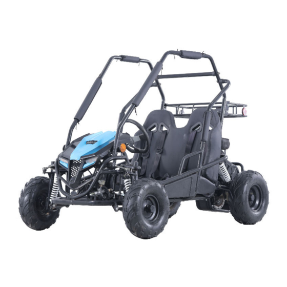
Page 2: Removal From Crate
REMOVAL FROM CRATE 1. Remove the metal crate Wheel Parts from the Go-Kart. 2. Locate and Remove Owner’s/Operator’s manual, set up instructions and all documentation. Rear Tires Note: Read Owner’s / Operator’s manual thoroughly before starting Go-Kart for the first time. 3. - Page 3 Brush Guard Parts Main Brush Guard Brush Guard Cross Braces Brush Guard Side Support Safety Belt Seat Safety Net...
-
Page 4: Rear Wheel Assembly
REAR WHEEL ASSEMBLY Hardware: M20 Washer 2ea. (1) M20 Castle nuts 2ea. (2) Cotter pins 2ea. (3) 2ea. (4) M20 Large Washer 1.Lift the Kart with a jack. Note: Make sure tire tread faces forward and Air valve stem is on the outside of the tire when installing. -
Page 5: Front Wheel Assembly
FRONT WHEEL ASSEMBLY Hardware: M14 Washer 2ea. (1) M14 Castle nuts 2ea. (2) 2ea. (3) Cotter pins M14 Large 2ea. (4) Washer 1. Lift the Kart with a jack. Make sure tread faces forward 2. Install the front wheel assembly in the following order. -
Page 6: Steering Wheel Installation
STEERING WHEEL INSTALLATION Hardware: M6X16 Bolts 3ea.(1) M6 Nuts 3ea.(2) 1. Attach steering wheel using M6 bolts (1) and M6 nuts (2). 2. Attach steering wheel cap by snapping into place on center of steering wheel. Steeling Wheel... -
Page 7: Seat Installation
SEAT INSTALLATION Hardware: M8 x 35 bolts 2 ea. (1) M8 Nuts 2 ea. (2) 1. To install the seat, attach the barb, located on the bottom of the seat, to the barb bracket on the Go Kart before attaching the bolt. 2. - Page 8 BRUSH GUARD INSTALLATION Hardware: M8 X bolts 4 ea. (1) M8 X 20 bolts 12ea. (2) M8 Concave Washers 4 ea. (3) 1.Attach Main Brush Guard withM8x20 bolts. Note:Do not tighten bolts at this time,keep bolts loose until the brush guard is completely assembled.
- Page 9 REAR SAFETY NET 1.Attach safety net on brushguard.
- Page 10 REAR RACK INSTALLATION Hardware: M8x16 bolts ea.(1) M8 nuts 4 ea. (2) Assemble the rear rack to the roll mounting point with Flange bolt M8x16(1)and nut M8.
-
Page 11: Pre-Ride Inspection
PRE-RIDE INSPECTION Inspecting and checking the WHAT TO CHECK FOR CHECK condition of the Go Kart before each ride is important. Steering • Smoothness • No restriction of Following the pre-ride check movement list will help insure the you do Brakes •...
Need help?
Do you have a question about the GK200 and is the answer not in the manual?
Questions and answers
Coleman Powersports GK200 Go-Kart Keeps stalling and the engine dies. Brand new