Table of Contents
Advertisement
Quick Links
INSTRUCTION MANUAL
INSTALLATION | WIRING | COMMISSIONING | MAINTENANCE |
I S O 9 0 0 1
ISO 14001
Q u a l i t é
Environnement
AFNOR CERTIFICATION
AFNOR CERTIFICATION
UTBS ECOWATT
PRO-REG
®
CORRIGO ETD2 regulation
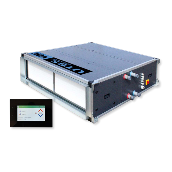
Regulated single flow air handling unit (AHU)
Compact unit for false ceiling
NT00000850-UTBS-ECOWATT-PRO-REG-ETD2-AN-230623
Advertisement
Table of Contents

Related Manuals for ViM UTBS ECOWATT PRO-REG


Summary of Contents for ViM UTBS ECOWATT PRO-REG
- Page 1 INSTRUCTION MANUAL INSTALLATION | WIRING | COMMISSIONING | MAINTENANCE | I S O 9 0 0 1 ISO 14001 Q u a l i t é Environnement AFNOR CERTIFICATION AFNOR CERTIFICATION UTBS ECOWATT PRO-REG ® CORRIGO ETD2 regulation Regulated single flow air handling unit (AHU) Compact unit for false ceiling NT00000850-UTBS-ECOWATT-PRO-REG-ETD2-AN-230623...
-
Page 2: Table Of Contents
SOMMAIRE GENERAL ............................4 Warnings ..........................4 Safety instructions ........................4 Reception – Storage ......................... 5 Warranty ........................... 5 PRODUCT RANGE PRESENTATION ....................5 Range ............................5 Main components ........................7 Functional synoptics (examples) ....................8 INSTALLATION ..........................12 Machine identification ......................12 Dimensions and weights...................... - Page 3 11. MAINTENANCE - REPLACEMENT OF PARTS - ALARMS ............57 11.1 Safety instructions ........................57 11.2 Maintenance frequency ......................58 11.3 Maintenance / replacement of fresh air filters................. 59 11.4 Maintenance / resetting / replacing the electric heater ............60 11.5 Maintenance / replacement of the water coil ................
-
Page 4: General
This product has been manufactured in compliance with rigorous technical safety rules, according to CE standards. The CE declaration and the manual can be downloaded from the website www.vim.fr. Before installing and using this product, carefully read these instructions which contain important infor- mation for your safety and that of users during the installation, commissioning and maintenance of this product. -
Page 5: Reception - Storage
- An automatic reset thermostat switches off the heater at 60°C. • Any resetting or tripping information (via the BMS for example) involves looking for the cause of this triggering on the AHU and on the installation. Contact sav@vim.fr. 1.3 Reception – Storage... - Page 6 • Variable airflow (VAV), constant airflow (CAV), constant pressure (COP). • Temperature control by the VIM specific integrated CORRIGO programmable logic controller. • Modbus communicating - ready to be connected control on port RS485 and BACnet IP on port TCP/IP.
-
Page 7: Main Components
Front and side rain Roof VF / VL protection Base frame 2-way mixing module Flexible rectangular Plenum module connection M0. VTVS 2-way or 3-way constant Silencer module VDVP pressure valves Motorizable rectangular damper. Air inlet ID + actuator Standard siphon to SIPH mounting to ensure frost (accessory) -
Page 8: Functional Synoptics (Examples)
2.3 Functional synoptics (examples) Configuration with electric heater (EI / EIF) Accessory Accessoire Sou age air neuf Supply air Prise air neuf Outdoor intérieur extérieur Accessory Accessoire fresh air S2/S3 SCO2 SPRD Triac ETD2 Accessory Accessoire Prise air neuf Outdoor extérieur fresh air Sou age air neuf... - Page 9 Configuration with hot and/or cold water coils (EC / EIF / ECF) Accessory Accessoire Sou age air neuf Supply air intérieur Bat 1 Bat 2 Accessory Prise air neuf Outdoor Accessoire extérieur S2/S3 M4 fresh air SPRD SCO2 ETD2 Accessory Accessoire Accessory Accessoire...
- Page 10 Configuration with reversible water coil (ER) Accessory Accessoire Sou age air neuf Supply air Bat 1 intérieur Accessory Accessoire Prise air neuf Outdoor extérieur S2/S3 fresh air SPRD SCO2 ETD2 Accessoire Accessory Accessory Accessoire Prise air neuf Outdoor extérieur fresh air Sou age air neuf Supply air Bat 1...
- Page 11 Configuration with direct expansion coil (EX) Accessory Accessoire Sou age air neuf Supply air intérieur Accessory Accessoire Prise air neuf Outdoor extérieur S2/S3 fresh air SPRD SCO2 ETD2 Groupe DX kit Kit DX unit Accessory Accessoire Prise air neuf Outdoor extérieur fresh air Sou age air neuf...
-
Page 12: Installation
INSTALLATION 3.1 Machine identification Identification label stuck on the panel of the fan box. 3.2 Dimensions and weights Configuration 3 Configuration 4 Configuration 5 Configuration 6 ER4 ou ER6 EC2 ou EC4 F M5 EF4 ou EF6 EC2 EF4 ou EF6 EX4 ou EX6 Configuration 7 F M5... - Page 13 Configuration 3 1454 1394 Configuration 4 1454 3/4" 1394 722,5 Dimensions (mm) and Weight (Kg) Config. 3 Config. 4 Connection Weight Weight Size 2-4 rows / (") 2 rows / 4 rows / 6 rows water coil 4 rows 6 rows 80 / 120 1-1/4"...
- Page 14 Configuration 5 1454 3/4" 723,5 1394 Configuration 6 1454 3/4" 1394 Dimensions (mm) and Weight (Kg) Config. 5 Config. 6 Connection BF weight Weight Size 2-4 rows/ (") 4 rows / 4 rows / 6 rows water coil 6 rows 6 rows 80 / 120 1-1/4"...
- Page 15 Configuration 7 1205 1145 Dimensions (mm) and weight (Kg) Config. 7 Size Weight 1 100 1 040 1 140 1 500 1 440 1 540 1 900 1 840 1 940 Accessories Connection flanges UTBS size 1040 1440 1840 CM - 2-way mixing modules 2MA* 2MB - 2MD - 2ME UTBS...
- Page 16 PB - Plenum module for horizontal installations UTBS size Total weight (kg) PB-V and PB-VR - Plenum modules with grille for vertical installations UTBS size 1100 1172 1500 1572 1900 1972 SIL - Silencer module Length 750mm Longueur UTBS Baffles 600 mm size Number of Baffles Total weight (kg)
- Page 17 TM - Antivibration suspension Number UTBS Rated load Elongation size Designation (kg) (mm) module TM-50 21-27 TM-50 21-27 TM-75 21-27 TM-100 21-27 Fixing bracket Base frame UTBS Use case size 2MB-D-E SIL Config. 1 Config. 2 Config. 7 1 207 Config.
-
Page 18: Handling And Lifting
3.3 Handling and lifting The units are delivered screwed onto pallets made to the dimensions of the box. The handling of UTBS ECOWATT air handling units can ® be done by pallet truck, forklift or crane. The handling equipment will be adapted to the load and the lifting conditions. - Page 19 G-versions Versions G Connexions on the left side Servitudes à gauche Accès aux ltres, panneau de contrôle Access to filters, control panel et raccordements batterie d’eau and water coil (lorsqu’elle existe) Access to filters and motors Accès aux ltres et moteurs D-versions Versions D Accès au moteurs...
-
Page 20: Fitting Accessories
3.5 Fitting accessories Antivibratiles Manchette souple Flexible connection Silencieux Silencer Visière Cover UTBS Servomoteur Actuator Registre Register UTBS Anti-vibration Damper Actuator Flexible connection Silencer Cover Register size support (4 units) JF-UTBS 650x250 SIL-2 750 PTMZ 50 VF UTBS-2 ID 2 JF-UTBS 1000x300 SIL-3 750 PTMZ 50... - Page 21 3.5.2 Flanges Remove the flange on the side where the accessory module UTBS module are delivered with flanges mounted. will be mounted. The result is an assembly of two modules with inlet and On the accessory module, mount the flange that was outlet flanges: previously removed from the UTBS module.
-
Page 22: Hydraulic And Fluid Connection
3.5.5 Mixing module The mixing module must be mounted at the air inlet of AHU and allows fresh outside air to be mixed with recycled air thanks to dampers placed on each air intake and controlled by proportional regulation. The mixing module and actuators are supplied as accessories. -
Page 23: Connection Of Hydraulic Accessories
The connection of the piping to the coil must not impose any mechanical, vibratory or thermal constraints (expansion). While tightening onto the coil thread, hold the tubing on the opposite di- rection, using for example a pin spanner, to prevent damage to the tubes by twisting. -
Page 24: Connection Of Direct Expansion Coils (Dx)
4.3 Connection of direct expansion coils (DX) Coil specifications 4 rows DX coils Volume Number of Ø liquid Ø gas Cooling Heating Air flow UTBS size circuit distributor manifold power (kW) power (kW) 1/2" (13mm) 3/4" (19mm) 1 250 2,21 5/8"... -
Page 25: Condensate Drain
4.4 Condensate drain It is essential to install a siphon with a difference in level greater than the available pressure of the fan (in mm CE) so that the condensate drains from the tray are done correctly. The drainage network must provide a minimum slope of approximately 2%. -
Page 26: Air Duct Connection
Installation with mixing module (percentage of recirculated air) SUPPLY INSUFFLATION OUTDOOR INDOOR EXTÉRIEUR INTÉRIEUR The versions with hot water coil also have the water temperature sensor mounted on the coil return mani- fold. This probe, supplied fitted and wired, monitors the risk of the battery frosting and must not be mani- pulated under any circumstances. -
Page 27: Accessories Connection
5.2 Accessories connection Differential pressure probe - Operation in COP mode (Constant Pressure) For an operation at constant pressure, it is necessary to install a pressure sensor in the supply air duct at a minimum distance of twice the connection's diameter. 2xD mini Code Designation... -
Page 28: Corrlgo Controller - Technical Datas
E tool© configuration software Computer equipment required: MS Windows 2000, 8, 7, XP, Vista, Windows 7, Windows 8 or Windows 10 operating system available on www.vim.fr. 6.4 Remote control with ETD2 display - Connection The ETD2 remote control is delivered with a 10 m cable (extension possible up to 100 m) The cable type delivered with the remote control is a 26AWG (4x 0.129 mm²) fitted with a 4P4C (RJ9) connector on the... - Page 29 The ETD2 remote control is IP20, it is exclusively reserved for indoor use, protected from humidity. It is equipped with an internal temperature sensor, not used. If the regulation is controlled by a remote on/off (use of the dedicated contact input or controlled by BMS), once the settings have been made, the remote control can be disconnected and stored in the control box.
-
Page 30: Internal Electrical Board - Description And Connection
6.5 Internal electrical board - Description and connection Supply air temperature sensor Sonde T Sou age Indoor return air temperature sensor Sonde T Reprise Antifrost sensor (EC / EF / ER / ECF version only) Sonde antigel (version EC / EF / ER / ECF uniquement) Outdoor air temperature sensor Sonde T Extérieure Supply fan control... - Page 31 Terminal block Variable Digital inputs (on-off) 21 (24VDC) Additional alarm 10 23 (24VDC) Filter monitoring - pressure switch 25 (24VDC) Electric heater overheating alarm 27 (24VDC) Change-over thermostat 31 (24VDC) External Start / Stop Request 33 (24VDC) External PV/GV Request 35 (24VDC) Fire alarm / smoke extraction Terminal block...
-
Page 32: External Components Connection Diagrams (Examples)
6.6 External components connection diagrams (examples) Connection of components to control the ventilation mode Main components Fresh air damper +24VDC Servo-moteur actuator de registre air neuf Fdc A et B NF24A-S2* Fdc A and B NF24A-S2* (*): If a second damper is installed in the supply, supply by (*) : Si un second registre est installé... - Page 33 Following accessories can be connected to the CORRIGO: • CO2 sensor, for regulation according to the CO2 rate. • Optical sensor, for operation with presence detection (ON/OFF or PV/GV). • With the CVF potentiometer and switch accessory: - The potentiometer is used to regulate the airflow of the unit. - The switch to start/stop the unit (terminals 31 and +24VDC) or the switch to PV/GV (terminals 33 and +24VDC).
-
Page 34: Connecting Accessories For Temperature Control With Internal Coil
6.7 Connecting accessories for temperature control with internal coil For regulation according to an ambient temperature, a TG R5/PT1000 ambient temperature sensor (ac- cessory) must be added to terminals 3 and G0. The supply air and fresh air temperature sensor must remain connected in any case. -
Page 35: Control - Functional Analysis
Version Addition of heating or reversible external coil (0-10V) Add external cooling coil (0-10v) Control signal AO3 (cooling). Parallel connection. Control signal AO1 (Heating / Cooling following change-over). Parallel connection. Control signal AO3 (cooling). Direct connection. CONTROL - FUNCTIONAL ANALYSIS 7.1 Main elements of control CORRIGO CONTROL MAIN ELEMENTS... -
Page 36: Airflow Control Fan
CORRIGO CONTROL - Communication failure alarm between controller and remote control - Control of the risk of freezing on the water coil (opening of the valve, stop if the water temperature drops below 7°C in heating mode) - Alarm history COMMUNICATION - Remote control with graphic touch screen (ETD2) - MODBUS RTU as standard configuration (RS485) -
Page 37: Temperature Control
7.2.3 Constant pressure operation (COP) Recommended mode in multi-zone configuration, for variable airflow applications with ter- minal airflow modulation devices. VAV damper controlled by CO2 sensor or Registre à débit variable régulé par Sonde CO2 Reprise air vicié intérieur Extract air Optical Sensor external to the AHU. -
Page 38: Special Case: Temperature Control With Ex Direct Expansion Coil
• Supply air regulation with return air temperature control: The return air temperature is maintained at the set value by a cascade control of the return air temperature and the supply air temperature. The supply air temperature value is generated according to the difference between the temperature setpoint and the temperature value measured by the return air temperature sensor. -
Page 39: Heating Water Coil Frost Protection (Ec / Ecf / Er Versions)
7.5 Heating water coil frost protection (EC / ECF / ER versions) For heating coil frost protection, the return water temperature is transmitted to the controller by a TGA1 PT1000 sensor factory-fitted on the coil outlet manifold. The controller constantly generates a signal to the valve actuator allowing a sufficient water flow to prevent frost in the coil. -
Page 40: Input For External Fire Signal
7.7 Input for external fire signal The control is configured to receive a fire contact. If the fire input is activated (DI7), the unit is stopped. When the unit has been stopped by the fire input, it can only be restarted after an acknowledgment of the alarm. -
Page 41: Use Of Remote Control Etd2
USE OF REMOTE CONTROL ETD2 8.1 Presentation of the ETD2 remote control Homepage This window displays strictly essential information on the status of the unit. It is possible to switch to the other available windows by pressing the menu window icon If a menu includes several pages, up and down scroll windows appear on the right of the screen, al- lowing you to move from one window to another. -
Page 42: Stop The Air Handling Unit
Menu accessible with installer or factory password: Settings > with installer password Clock > with installer password Communication > with installer password Parameters and advanced settings > with factory password Registration > with installer password Synoptic display Press the icon from the main menu The synoptic is a graphical representation of the state of the unit, with the different components and their values. - Page 43 VAV MENU Allow: • to stop the unit > STOP • to operate automatically according to the signal from the air quality sensor or external 0-10 V signal • to manually select the GV speed (Airflow for Vmax set) • to manually select the BOOST speed •...
- Page 44 Alarm settings Press the icon from the main menu Allows you to view active alarms, acknowledge them or block them if necessary. Setting authority levels and passwords Press the icon from the main menu This page allows you to connect with a sufficient level of authority to perform certain functions.
-
Page 45: Specific Settings For Ventilation Modes Cav/Vav/Cop
8.4 Specific settings for ventilation modes CAV/VAV/COP Press the icon from the main menu > Installer level Access to this menu is used to modify the factory settings presented in § "10.1 AHU factory settings", page 56 Choice of fan control mode: •... - Page 46 8.4.2 Specific settings for VAV mode If Variable Airflow - VAV selected On this page you can enter: • The range of use of the connected air quality sensor Vmin and Vmax • The desired values in m³/h for the mini Vmin ECO, for the normal Vmax GV and the Extra m /h values.
- Page 47 8.4.3 Specific settings for COP mode • Enter the pressure setpoints in Pa in ECO and GV mode for the supply air fan. If you only have only one set point, enter the same value twice. Setting the fan(s): • K factor: see table § "Factory settings", page 56 •...
- Page 48 8.4.4 Settings common to all ventilation operating modes Press the icon from the main menu > Installer level This screen is used to configure the reaction of the fans when the "fire" digital input is activated. 3 options : • Operation at maximum airflow, •...
-
Page 49: Time Schedule
8.5 Time schedule Press the icon from the main menu > Installer level This menu allows you to define: • Date and time • Time schedules for unit operation • Automatic Winter/Summer time change Date / time menu Allows the regulation to be set to the correct time and date. It is possible to automatically activate summer/winter time changes. - Page 50 It is possible to set up to 4 time programs per day of the week + 1 Holiday day If the unit has been configured in CAV mode it is possible to select: • STOP / ECO / GV / BOOST If the unit has been configured in VAV mode it is possible to select: •...
-
Page 51: Setting The Communication Protocol
8.6 Setting the communication protocol Press the icon from the main menu > Installer level This menu contains the configuration settings for the MODBUS RS485 and MODBUS IP – BACNET MSTP – BACNET IP protocols. Communication to RS485 supervision must be done on communication port No.1. Allows selection of the desired protocol using the arrows: •... -
Page 52: Save And Restore
• To return to the configuration of the unit leaving the factory (default parameters CAV mode) • To record of factory settings, requires Expert level, only reserved for VIM after-sales service • Reset the CORRIGO makes to completely reload the unit's program ASR program for example. -
Page 53: Expert Level Settings
To load the last saved configuration: • Press the corresponding icon • A pop-up window appears asking you to validate your request. • A new window informs you when the operation is complete. 8.8 Expert level settings from the main menu > Expert level: factory password sent only by our af- Press the icon by ter-sales service This menu is used to view the status of the inputs/outputs,... - Page 54 MODBUS IP on port TCP/IP The CORRIGO controller has a TCP/IP communication port (RJ45 socket) allowing TCP/IP connection to a TCP/IP network. This port is by default dedicated to Modbus IP communication. Simplified MODBUS table The simplified Modbus list below includes the data most commonly used in supervision. All of these points can be obtained for all units fitted with CORRIGO controls.
- Page 55 Read/ Function Type Register Description Accepted values Write Supply air duct Pressure measured in the supply air duct pressure in COP Input register in COP mode 0...max of unit mode Values: 0 .. 9999 meaning 0 .. 999.9Pa Read forcing normal speed status Forcing normal Input Status 0=forcing normal speed not active;...
-
Page 56: Communication In Bacnet Protocol
9.2 Communication in BACnet protocol BACnet MS/TP on port 2 – RS485 The CORRIGO controller is equipped by two RS485 communication ports (to be used with an STP cable). Port 2 is by default dedicated to BACnet MS/TP communication, but the function must be activated in order to operate. -
Page 57: Factory Control Of Air Handling Units
The commissioning and setting of the control must be carried out by a qualified person. In France, this service can be provided by VIM and its qualified service providers. Contact sav@vim.fr. This service can only intervene once the installation, the electrical, aeraulic and hydraulic connection operations have been carried out. -
Page 58: Maintenance Frequency
- An automatic reset thermostat switches off the heater at 60°C. • Any resetting or tripping information (via the BMS for example) involves looking for the cause of this triggering on the AHU and on the installation. Contact sav@vim.fr. 11.2 Maintenance frequency Comply with legal obligations as a minimum. -
Page 59: Maintenance / Replacement Of Fresh Air Filters
11.3 Maintenance / replacement of fresh air filters When starting-up for the first time, once the installation is complete, it is advisable to clean the filters or even replace them. As standard, the UTBS ECOWATT PRO-REG include: ® • an M5 pre-filter on the fresh air •... -
Page 60: Maintenance / Resetting / Replacing The Electric Heater
If the unit is equipped with a pre- Remove filters. filter, it is necessary to remove the guide support to release the filters. 11.4 Maintenance / resetting / replacing the electric heater Before winter, dust off heating elements with compressed air or using a vacuum cleaner and a soft brush. •... -
Page 61: Corrigo Controller - Reset And Battery Replacement
After removal, the coil can be cleaned with a jet of water, steam or compressed air, proceed with care as not to damage the coil's fins. For units equipped with reversible cooling coils (ER), clean the condensate pan by using water and a non-abrasive detergent. - Page 62 Press the icon from the main menu Press "Reset CORRIGO" Wait for the end of the reset time The screen used to choose the program to load into the controller appears: • Press "Load" • Select "SIMPLE FLUX" program used for the UTBS •...
-
Page 63: Alarms And Faults
Battery replacement - type CR2032 When the low battery alarm appears and the red indicator light turns on, it means that the backup battery for memory backup and real-time clock is too low. A capacitor saves the memory and keeps the clock running for about 10 minutes after the power is turned off. -
Page 64: List Of Main Spare Parts
Les prés de Mégy Sud – SOUDAN CS 60120 - 79401 ST MAIXENT L’ECOLE CEDEX Tél. : 05 49 06 60 38 or 05 49 06 60 25 sav@vim.fr - www.vim.fr 64/64 NT00000850-UTBS-ECOWATT-PRO-REG-ETD2-AN-230623...
Need help?
Do you have a question about the UTBS ECOWATT PRO-REG and is the answer not in the manual?
Questions and answers